
Section
2 Definitions and symbols
2.1 Parameters to be used for the determination of load and design
criteria
2.1.1
Air
gap. The air gap, G
A, is the minimum
vertical distance, in metres, from the static waterline to the point
considered in an operational condition. In no case is G
A to be taken greater then G
A(max) as
indicated in Figure 2.2.1 Definition of air gap.

Figure 2.2.1 Definition of air gap
2.1.2
Allowable
speed V.
The allowable speed used in the computation
of environmental loads is the design speed, in knots, associated with
a nominated operational environment in which the craft is certified
at corresponding operational displacement.
2.1.3
Beaufort
Number. Beaufort Number is a measure of wind strength.
2.1.4
Bilge
tangential point. For craft with partially submerged hull(s),
the bilge tangential point is defined as the tangential point of the
bilge with an oblique line sloped at 50o to the horizontal
at the LCG, see
Figure 2.2.2 Definition of bilge tangential point and G
s for
craft with partially submerged hulls
.
For craft with fully submerged hull(s), the bilge tangential point
is defined as the intersection points between the hull and the design
waterline.

Figure 2.2.2 Definition of bilge tangential point and G
s for
craft with partially submerged hulls
2.1.5
Deadrise
angle. For craft with no clearly defined deadrise angle at
the LCG, the angle, in degrees, to the horizontal of the line at the
LCG formed by joining the lowest point of the hull or underside of
keel and the bilge tangential point is to be taken as the deadrise
angle θD, see
Figure 2.2.2 Definition of bilge tangential point and G
s for
craft with partially submerged hulls
. For craft with hulls of
asymmetric section, where the inner and outer deadrise angles differ,
the smaller of the two angles is to be used. For craft with fully
submerged hull with circular sections, the deadrise angle is to be
taken as 30o.
2.1.6
Displacement
mode. Displacement mode means the regime, whether at rest or
in motion, where the weight of the craft is fully or predominantly
supported by hydrostatic forces.
2.1.7
Froude
Number F
n.
The Froude Number is a non-dimensional
speed parameter and is defined as:
2.1.8
LCG. The
LCG is the longitudinal centre of gravity of the craft in the loading
condition under consideration.
2.1.9
Maximum
wave height. In general the maximum wave height, in metres,
will be taken as 1,667 times the significant wave height. Where, for
design purposes, a wave length is required this will be taken as the
waterline length subject to any restriction resulting from limiting
height to length ratio and wave profile angle.
2.1.10
Non-displacement
mode. Non-displacement mode means the normal operational regime
of a craft when non-hydrostatic forces substantially or predominantly
support the weight of the craft.
2.1.11
Operating
waterline is the waterline for the operating condition under
consideration.
2.1.12
Period. The period is defined as the average time interval between
upward crossings of the mean value.
2.1.13
Sea
state. Sea state is an expression used to categorise wave conditions
and is normally defined by sea spectrum, significant wave height and
period distribution.
2.1.14
Significant
wave height H
1/3.
The wave height,
in metres, used in the determination of craft motions and loads is
a significant wave height, H
1/3, defined as
the average of the one third highest waves in a short term wave measurement
record.
2.1.16
Surviving
wave height H
03.
The wave height, in
metres, used in the determination of the structural integrity of a
craft and is defined as the wave height with three per cent probability
of exceedance. If this value is unknown, the following equation is
to be used to determine H
03:
2.1.18
Volumetric
speed number F
v.
The Volumetric speed
number is defined as:
where ∇ is the moulded displacement, in m3,
of the craft corresponding to the design waterline.
2.1.20
Protected
structure, see
Figure 2.2.3 Definition of wet-deck protected and unprotected structure. A protected structure is one in which the wet-deck component
under consideration is enclosed by port and starboard side inboard
structure, where `side inboard' is as defined in Ch 4,1.5.6 of Parts Pt 6, Ch 4, 1.5 Symbols and definitions 1.5.6, Pt 7, Ch 4, 1.5 Symbols and definitions 1.5.6 and Pt 8, Ch 4, 1.5 Symbols and definitions 1.5.6 for craft of steel, aluminium alloy
and composite construction respectively.
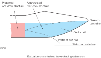
Figure 2.2.3 Definition of wet-deck protected and unprotected structure
2.1.21
Unprotected
structure, see
Figure 2.2.3 Definition of wet-deck protected and unprotected structure. An unprotected structure is one in which the wet-deck
component under consideration is not enclosed by port and starboard
side inboard structure, where `side inboard' is as defined in Ch 4,1.5.6
of Parts Pt 6, Ch 4, 1.5 Symbols and definitions 1.5.6, Pt 7, Ch 4, 1.5 Symbols and definitions 1.5.6 and Pt 8, Ch 4, 1.5 Symbols and definitions 1.5.6 for
craft of steel, aluminium alloy and composite construction respectively.
2.2 Symbols
2.2.1
LR, B, D, Cb, LWL
and T are as defined in Pt 3, Ch 1, 6.2 Principal particulars.
|
x
wI
|
= |
longitudinal distance, in metres, measured forwards from the
aft end of the L
WL to the position or centre
of gravity of the item being considered
|
|
z
|
= |
vertical
distance, in metres, from the baseline to the position of centre of
gravity of the item being considered. z is positive above
the baseline
|
| = |
Normally the following definitions are to be applied: |
| = |
z is to be taken at one third of the panel or strake
height
|
| = |
For short stiffener members: z is to be taken at
the stiffener mid position
|
| = |
For long stiffener members: z is generally to be
taken at the stiffener mid position, but may need to be specially
considered, especially when there is a significant pressure variation
along its length
|
|
Tx
|
= |
local draught measured from the underside of the keel to the
operating waterline at the longitudinal position under consideration see
Figure 2.2.1 Definition of air gap
|
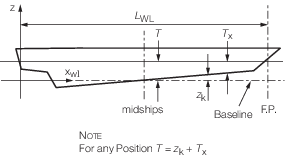
Figure 2.2.4 Definition of Symbols
2.2.2 The displacement, Δ,
in tonnes, used in this Part is the mass of the craft in the loading
condition under consideration.
2.3 Minimum significant wave height
2.3.1 The minimum
value of significant wave height, H
1/3, see
Pt 5, Ch 2, 2.1 Parameters to be used for the determination of load and design criteria 2.1.14, in metres, used
in the determination of accelerations and loads is, in general, not
to be taken less than that given in Table 2.2.1 Minimum significant wave height,
H
1/3
for the appropriate Service Groups defined in Pt 1, Ch 2, 3.5 Service area restriction notations.
2.3.2 The designer/Builder
is to provide the value of significant wave height for use in the
determination of the Rule loadings and, further, is to ensure that
such a wave height is appropriate to the intended area of operation
and/or service. In this respect the statistical wave data may be required
to be submitted in support of the wave height nominated.
2.3.3 A reduction
in the minimum value of significant wave height for a particular Service
Group will be specially considered, provided that satisfactory statistical
wave data for the intended service area are submitted for approval. See also
Pt 5, Ch 2, 2.1 Parameters to be used for the determination of load and design criteria 2.1.14.
Table 2.2.1 Minimum significant wave height,
H
1/3
| Service Group
|
Minimum significant
wave height, in metres
|
| 1
|
0,6
|
| 2
|
1,0
|
| 2A
|
1,5
|
| 3
|
2,0
|
| 4
|
4,0
|
| 5
|
4,0
|
| 6
|
4,0
|
|