
Section
7 Construction
7.1 Access arrangements
7.1.1 Pressure
vessels are to be so made that the internal surfaces may be examined.
Wherever practicable, the openings for this purpose are to be sufficiently
large for access and for cleaning the inner surfaces.
7.1.2 Manholes
in cylindrical shells should preferably have their shorter axes arranged
longitudinally.
7.1.3 Doors
for manholes and sightholes are to be formed from the steel plate
or of other approved construction, and all jointing surfaces are to
be machined.
7.1.4 Doors
of the internal type are to be provided with spigots which have a
clearance of not more than 1,5 mm all round, i.e. the axes of opening
are not to exceed those of the door by more than 3 mm. The width of
the manhole gasket seat is not to be less than 16 mm.
7.1.5 Doors
of the internal type for openings not larger than 230 x 180 mm need
be fitted with only one stud, which may be forged integral with the
door. Doors for openings larger than 230 mm x 180 mm are to be fitted
with two studs or bolts. The strength of the attachment to the door
is not to be less than the strength of the stud or bolt.
7.1.6 The crossbars
or dogs for doors are to be of steel.
7.1.7 External
circular flat cover plates are to be in accordance with a recognised
standard.
7.2 Torispherical and semi-ellipsoidal ends
7.2.2 Where
the difference in thickness is the same throughout the circumference,
the thicker plate is to be reduced in thickness by machining to a
taper for a distance not less than four times the offset, so that
the two plates are of equal thickness at the position of the circumferential
weld. A parallel portion may be provided between the end of the taper
and the weld edge preparation; alternatively, if so desired, the width
of the weld may be included as part of the smooth taper of the thicker
plate.
7.2.3 The thickness
of the plates at the position of the circumferential weld is to be
not less than that of an unpierced cylindrical shell of seamless or
welded construction, whichever is applicable, of the same diameter
and material, see
Pt 15, Ch 4, 2.1 Minimum thickness.
7.3 Welded-on flanges, butt welded joints and fabricated branch pieces
7.3.1 Flanges
may be cut from plates or may be forged or cast. Hubbed flanges are
not to be machined from plate. Flanges are to be attached to branches
by welding. Alternative methods of flange attachment will be subject
to special consideration.
7.3.2 The types
of welded-on flanges are to be suitable for the pressure, temperature
and service for which the branches are intended.
7.3.3 Flange
attachments and pressure-temperature ratings in accordance with materials
and design of recognised standards will be accepted.
7.3.5 Welded-on
flanges are not to be a tight fit on the branch. The maximum clearance
between the bore of the flange and the outside diameter of the branch
is to be 3 mm at any point, and the sum of the clearances diametrically
opposite is not to exceed 5 mm.
7.3.6 Where
butt welds are employed in the attachment of flange type (a), or in
the construction of standpipes or branch pieces, the adjacent pieces
are to be matched at the bores. This may be effected by drifting,
roller expanding or machining, provided the pipe wall is not reduced
below the designed thickness. If the parts to be joined differ in
wall thickness, the thicker wall is to be gradually tapered to that
of the thinner at the butt joint.
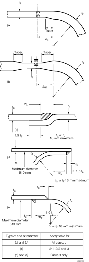
Figure 4.7.1 Typical attachment of dished ends to cylindrical shell
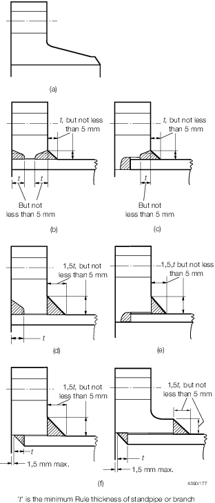
Figure 4.7.2 Typical example of welded flange connections
7.3.7 Welding
may be carried out by means of the shielded metal arc, inert gas metal
arc, oxy-acetylene or other approved process, but in general, oxy-acetylene
welding is suitable only for flange type (a) and is not to be applied
to branches exceeding 100 mm diameter or 9,5 mm thick.
7.3.9 Socket
weld joints are not to be used where fatigue, severe erosion, crevice
corrosion or stress corrosion are expected to occur, for example,
blow down, drain, scum and chemical dosing connections.
7.4 Welded attachments to pressure vessels
7.4.1 Unless
the actual thickness of the shell or end is at least twice that required
by calculation for a seamless shell or end, whichever is applicable,
doubling plates with well rounded corners are to be fitted in way
of attachments such as lifting lugs, supporting brackets and feet,
to minimise load concentrations on pressure shells and ends. Compensating
plates, pads, brackets and supporting feet are to be bedded closely
to the surface before being welded, and are to be provided with a
`tell-tale' hole not greater than 9,5 mm in diameter, open to the
atmosphere to provide for the release of entrapped air during heat
treatment of the vessel, or as a means of indicating any leakage during
hydraulic testing and in service.
7.4.2 For acceptable
methods of attaching standpipes, branches, compensating plates and
pads, see
Figure 4.7.3 .
Alternative methods of attachment may be accepted provided details
are submitted for consideration.
7.4.3 Where
fillet welds are used to attach standpipes, there are to be equal
sized welds both inside and outside the vessel shell, see
Figure 4.7.3 (a) and (l). The leg length
of each of the fillet welds is to be not less than the actual thickness
of the thinner of the parts being joined.
Table 4.7.1 Limiting design conditions for
flanges
| Flange type
|
Maximum pressure
|
Maximum
temperature
|
Maximum pipe
o.d.
|
Minimum pipe
bore
|
|
|
|
oC
|
mm
|
mm
|
| (a)
|
Pressure
temperature ratings to be in accordance with a recognised Standard
|
No restriction
|
No restriction
|
No restriction
|
| (b)
|
Pressure
temperature ratings to be in accordance with a recognised Standard
|
No restriction
|
168,3 for alloy
steels*
|
No restriction
|
| (c)
|
Pressure
temperature ratings to be in accordance with a recognised Standard
|
No restriction
|
168,3 for alloy
steels*
|
75
|
| (d)
|
Pressure
temperature ratings to be in accordance with a recognised Standard
|
425
|
No restriction
|
No restriction
|
| (e)
|
Pressure
temperature ratings to be in accordance with a recognised Standard
|
425
|
No restriction
|
75
|
| (f)
|
Pressure
temperature ratings to be in accordance with a recognised Standard
|
425
|
No restriction
|
No restriction
|
Note
* No restriction for carbon steels
|
|
| Copyright 2022 Clasifications Register Group Limited, International Maritime Organization, International Labour Organization or Maritime
and Coastguard Agency. All rights reserved. Clasifications Register Group Limited, its affiliates and subsidiaries and their respective
officers, employees or agents are, individually and collectively, referred to in this clause as 'Clasifications Register'. Clasifications
Register assumes no responsibility and shall not be liable to any person for any loss, damage or expense caused by reliance
on the information or advice in this document or howsoever provided, unless that person has signed a contract with the relevant
Clasifications Register entity for the provision of this information or advice and in that case any responsibility or liability is
exclusively on the terms and conditions set out in that contract.
|
 |
|