
Section
4 Dished ends subject to internal pressure
4.1 Minimum thickness
4.1.1 The thickness, t, of semi-ellipsoidal and hemispherical unstayed ends, and
the knuckle section of torispherical ends, dished from plate, having
pressure on the concave side and satisfying the conditions listed
below, is to be determined by the following formula:
4.1.2 For semi-ellipsoidal
ends:
the external height, H ≥ 0,18 D
o
where
|
D
o
|
= |
the external diameter of the parallel portion of the end, in
mm. |
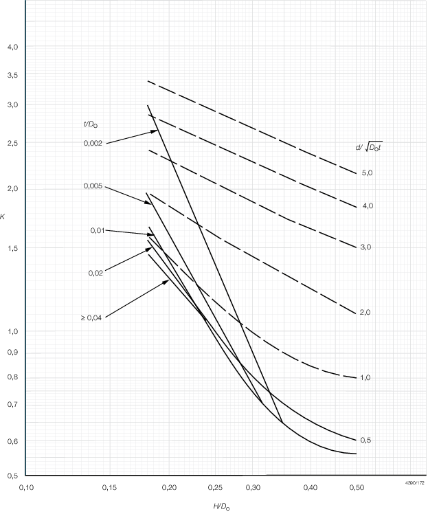
Figure 4.4.1 Shape Factor
4.1.3 For torispherical
ends:
- the internal radius, R
i ≤ D
o
- the internal knuckle radius, r
i ≥ 0,1D
o
- the internal knuckle radius, r
i ≥ 3t
- the external height, H ≥ 0,18 D
o and
is determined as follows:
4.1.4 In addition
to the formula in Pt 15, Ch 4, 4.1 Minimum thickness 4.1.1 the
thickness, t, of a torispherical head, made from more
than one plate, in the crown section is to be not less than that determined
by the following formula:
where t, p, R
i, σ and J are as defined in Pt 15, Ch 4, 1.7 Definition of symbols.
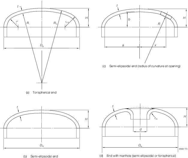
Figure 4.4.2 Typical dished ends
4.1.8 For ends
which are butt welded to the shell the thickness of the edge of the
flange for connection to the shell is to be not less than the thickness
of an unpierced seamless or welded shell, whichever is applicable,
of the same diameter and material and determined by Pt 15, Ch 4, 2.1 Minimum thickness.
4.2 Shape factors for dished ends
4.3 Dished ends with unreinforced openings
4.3.1 Openings
in dished ends may be circular, obround or approximately elliptical.
4.3.2 The upper
curves in Figure 4.4.1 Shape Factor provide
values of K, to be used in Pt 15, Ch 4, 4.1 Minimum thickness 4.1.1, for ends with unreinforced openings. The selection of the
correct curve depends on the value of  and a trial calculation is necessary to select the correct
curve, and a trial calculation is necessary to select the correct
curve,
where
|
d
|
= |
the
diameter of the largest opening in the end plate, in mm (in the case
of an elliptical opening, the larger axis of the ellipse) |
|
t
|
= |
minimum
thickness, after dishing, in mm |
|
D
o
|
= |
outside diameter of dished end, in mm |
4.3.3 The following
requirements must in any case be satisfied:
4.4 Flanged openings in dished ends
4.4.2 Where
openings are flanged, the radius, r
m of the
flanging is to be not less than 25 mm, see
Figure 4.4.2 Typical dished ends. The thickness of the
flanged portion may be less than the calculated thickness.
4.5 Location of unreinforced and flanged openings in dished ends
4.5.1 Unreinforced
and flanged openings in dished ends are to be so arranged that the
distance from the edge of the hole to the outside edge of the plate
and the distance between openings are not less than those shown in Figure 4.4.3 Limits for reinforcement.
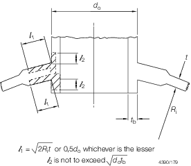
Figure 4.4.3 Limits for reinforcement
4.6 Dished ends with reinforced openings
4.6.1 Where
it is desired to use a large opening in a dished end of less thickness
than would be required by Pt 15, Ch 4, 4.3 Dished ends with unreinforced openings,
the end is to be reinforced. This reinforcement may consist of a ring
or standpipe welded into the hole, or of reinforcing plates welded
to the outside and/or inside of the end in the vicinity of the hole,
or a combination of both methods, see
Figure 4.4.4 Opening in dished ends. Forged reinforcements
may be used.
4.6.5 If the
material of the ring or the reinforcing plates has an allowable stress
value lower than that of the end plate, then the effective cross-sectional
area, A, is to be multiplied by the ratio:
4.7 Torispherical dished ends with reinforced openings
4.7.1 If an
opening and its reinforcement are positioned entirely within the crown
section, the compensation requirements are to be as for a spherical
shell, using the crown radius as the spherical shell radius. Otherwise,
the requirements of Pt 15, Ch 4, 4.6 Dished ends with reinforced openings are to
be applied.
|