
Section
7 Control and monitoring of main, auxiliary and emergency engines
7.1 General
7.1.2 Oil mist detection or bearing temperature monitoring (or equivalent device
in accordance with SOLAS II-1, Regulation 47 - Fire precautions, 47.2) fitted as required by Pt 10, Ch 1, 10.8 Oil mist detection 10.8.1 are to operate as follows:
- For trunk piston engines automatic shutdown of the engine is to occur when oil mist
or high bearing temperature is detected.
- For crosshead engines, automatic slow-down is to occur when oil mist or high bearing
temperature is detected.
- Where arrangements are made to override the automatic shutdown due to high oil mist
or bearing temperature, the override is to be independent of other overrides.
- Where the bearing temperature monitoring method is chosen, all bearings in the
crankcase are to be monitored where practicable, e.g. main, crankpin, crosshead.
- Where engine bearing temperature monitors or equivalent devices in
accordance with SOLAS II-1, Regulation 47 - Fire precautions, 47.2 are provided for the prevention of the
build-up of oil mist that may lead to a potentially explosive condition within the
crankcase, details are to be submitted for consideration. The submission is to
demonstrate that the arrangements are equivalent to those provided by oil mist
detection, see
Pt 10, Ch 1, 10.8 Oil mist detection 10.8.15.
Where required, for each trunk piston engine, one oil mist detector (or
engine bearing temperature monitoring system or equivalent device) having two
independent outputs for initiating the alarm and shutdown would satisfy the requirement
for independence between alarm and shutdown systems.
7.1.3 All main
and auxiliary engines intended for essential services are to be provided
with means of indicating the lubricating oil pressure supply to them.
Where such engines are of more than 220 kW, audible and visual alarms
are to be fitted to give warning of an appreciable reduction in pressure
of the lubricating oil supply. Further, these alarms are to be actuated
from the outlet side of any restrictions, such as filters, coolers,
etc.
7.2 Main engine governors
7.2.1 An efficient governor is to be fitted to each main engine so adjusted that
the speed does not exceed that for which the engine is to be classed by more than 15 per
cent.
7.2.2 Engines coupled to electrical generators that are the source of power for
main electric propulsion are to comply with the requirements for electrical generator
engines in respect of governors and overspeed protection devices.
7.2.3 When electronic speed governors of main internal combustion engines form
part of a remote control system, they are to comply with the following conditions:
- If lack of power to the governor may cause changes in the
present speed and direction of thrust of the propeller, which consequently
compromise safe operation of the vessel, then backup power supply is to be
provided;
- Local control of the engines is always to be possible. A
means to effect safe transfer of control to the local control position and then
control the engine is to be available in all normal and reasonably foreseeable
abnormal conditions;
- In addition, electronic speed governors and their actuators
are to be type approved in accordance with LR’s Type Approval System Test
Specification Number 1.
7.3 Auxiliary and emergency engine governors
7.3.1 Prime movers for driving generators of the main and emergency sources of electrical
power are to be fitted with a speed governor which will prevent transient frequency
variations in the electrical network in excess of ±10 per cent of the rated frequency,
with a recovery time to steady state conditions not exceeding 5 seconds, when the
maximum electrical step load is switched on or off.
7.3.2 In the case when a step load equivalent to the rated output of a generator is switched
off, a transient speed variation in excess of 10 per cent of the rated speed may be
acceptable, provided that this does not cause the intervention of the overspeed device
as required by Pt 10, Ch 1, 7.4 Overspeed protective devices.
7.3.3 At all loads between no load and rated power, the permanent speed variation should not
be more than ±5 per cent of the rated speed.
7.3.4 Prime movers are to be selected in such a way that they will meet the load demand within
the ship’s power distribution system. Application of electrical load should be possible
with two load steps and must be such that prime movers, running at no load, can suddenly
be loaded to 50 per cent of the rated power of the generator followed by the remaining
50 per cent after an interval sufficient to restore the speed to steady state. Steady
state conditions should be achieved in not more than 5 seconds. Steady state conditions
are those at which the envelope of speed variation does not exceed +1 per cent of the
declared speed at the new power.
7.3.5 Application of electrical load in more than two load steps can only be
permitted if the conditions within the ship’s power distribution system permit the use
of such prime movers which can only be loaded in more than two load steps ( see
Figure 1.7.1 Reference values for maximum possible sudden power increase (four-stroke
engines)) and provided that this is already
allowed for at the design stage. This is to be verified in the form of system
specifications to be approved and to be demonstrated at ship’s trials. In this case, due
consideration is to be given to:
- The power required for the electrical equipment to be
automatically switched on after blackout and to the sequence in which it is
connected.
- Where generators are to be operated in parallel and where the
power has to be transferred from one generator to another in the event of any one
generator being switched off.
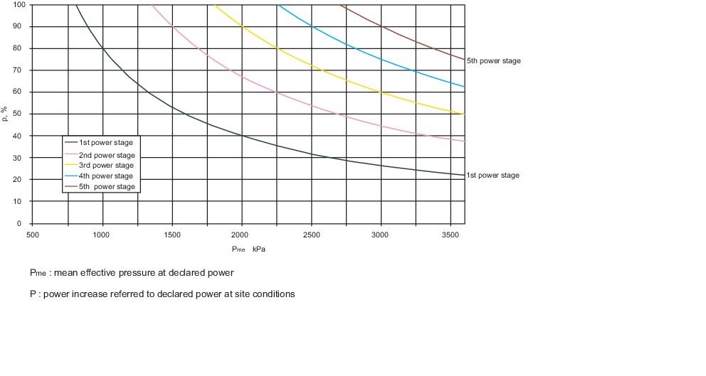
Figure 1.7.1 Reference values for maximum possible sudden power increase (four-stroke
engines)
7.3.6 Emergency generator sets are to comply with the requirements of Pt 10, Ch 1, 7.3 Auxiliary and emergency engine governors 7.3.1 to Pt 10, Ch 1, 7.3 Auxiliary and emergency engine governors 7.3.3 even when:
- their total consumer load is applied suddenly; or
- their total consumer load is applied in steps, subject to:
- the total load being supplied within 45 seconds of power
failure on the main switchboard;
- the maximum step load being declared and
demonstrated;
- the power distribution system being designed such that the
declared maximum step loading is not exceeded; and
- the compliance of time delays and loading sequence with
the above being demonstrated at ship’s trials.
7.3.7 For a.c. generating sets operating in parallel, the governing characteristics of the
prime movers shall be such that within the limits of 20 per cent and 100 per cent total
load, the load on any generating set will not normally differ from its proportionate
share of the total load by more than 15 per cent of the rated power of the largest
machine, or 25 per cent of the rated power of the individual machine in question,
whichever is the less. For an a.c. generating set intended to operate in parallel,
facilities are to be provided to adjust the governor sufficiently finely to permit an
adjustment of load not exceeding 5 per cent of the rated load at normal frequency.
7.4 Overspeed protective devices
7.4.1 Each main engine developing 220 kW or over which can be declutched or which
drives a controllable pitch propeller, also each auxiliary engine developing 220 kW and
over for driving an electric generator, is to be fitted with an approved overspeed
protective device.
7.5 Unattended machinery
7.5.1 Where main and auxiliary engines are fitted with automatic or remote
controls so that under normal operating conditions they do not require any manual
intervention by the operators, they are to be provided with the alarms and safety
arrangements required by Pt 10, Ch 1, 7.5 Unattended machinery to Pt 10, Ch 1, 7.7 Auxiliary engines as appropriate. Alternative
arrangements which provide equivalent safeguards will be considered.
7.5.2 Where machinery is arranged to start automatically or from a remote control station,
interlocks are to be provided to prevent start-up under conditions, which could cause a
hazard to the machinery and personnel.
7.5.3 Where machinery specified in this Section is required to be provided with a
standby pump, the standby pump is to start automatically if the discharge pressure from
the working pumps falls below a predetermined value.
7.5.4 Where a first stage alarm together with a second stage alarm and automatic
shutdown of machinery are required by in the relevant Tables of this Section and, the
sensors and circuits utilised for the second stage alarm and automatic shutdown are to
be independent of those required for the first stage alarm.
7.5.5 Means
are to be provided to prevent leaks from high pressure fuel oil injection
piping for main and auxiliary engines dripping or spraying onto hot
surfaces or into machinery air inlets. Such leakage is to be collected
and, where practicable, led to a collector tank(s) fitted in a safe
position. An alarm is to be provided to indicate that leakage is taking
place. These requirements may also be applicable to high pressure
hydraulic oil piping depending upon the location.
7.6 Engines for propulsion purposes
7.6.1 Alarms and safeguards are indicated in and Pt 10, Ch 1, 7.6 Engines for propulsion purposes 7.6.2 to Pt 10, Ch 1, 7.6 Engines for propulsion purposes 7.6.8 and
Table 1.7.1 Engines for propulsion purposes:
alarms and safeguards slow-downs and Table 1.7.2 Engines for propulsion purposes: Automatic shutdowns.
Table 1.7.1 Engines for propulsion purposes:
alarms and safeguards slow-downs
| Item
|
Alarm
|
Note
|
| Lubricating oil sump level
|
Low
|
Engines (and gearing if fitted)
|
| Lubricating oil inlet pressure*++
|
1st stage Low++
|
Engines (and gearing if fitted) Slow-down
|
| Lubricating oil inlet temperature*
|
High
|
Engines (and gearing if fitted)
|
| Lubricating oil filters differential pressure
|
High
|
-
|
| Activation of oil mist detection arrangements (or
activation of the temperature monitoring systems or equivalent devices of:
- the engine main, crank and crosshead bearing oil outlet; or
-
the engine main, crank and crosshead bearing)
|
High
|
For crosshead engines, automatic slow-down. For
trunk-piston engines, see
Table 1.7.2 Engines for propulsion purposes: Automatic shutdowns. See also
Pt 10, Ch 1, 7.1 General 7.1.2
|
| Cylinder lubricator flow
|
Low
|
One sensor per lubricator unit on crosshead engines.
Slow-down.
|
| Thrust bearing temperature*
|
High
|
Slow-down
|
| Piston coolant inlet pressure
|
Low
|
If a separate system. Slow-down
|
| Piston coolant outlet temperature*
|
High
|
Per cylinder (if a separate system). Slow-down
|
| Piston coolant outlet flow*
|
Low
|
Per cylinder (if a separate system)
|
| Cylinder coolant inlet pressure or flow*++
|
Low
|
Slow-down (automatic on trunk piston engines)
|
| Cylinder coolant outlet temperature*++
|
1st stage High++
|
Per cylinder (if a separate system) Slow-down
(automatic on trunk piston engines)++
|
| Engine cooling water system – oil content
|
High
|
Required for crosshead engines where engine cooling water used in
oil/water heat exchangers
|
| Sea-water cooling pressure
|
Low
|
-
|
| Fuel valve coolant pressure
|
Low
|
If a separate system
|
| Fuel valve coolant temperature
|
High
|
If a separate system
|
| Fuel oil pressure from booster pump
|
Low
|
-
|
| Fuel oil temperature or viscosity*
|
High and Low
|
Heavy oil only
|
| Fuel oil high pressure piping*
|
Leakage
|
See
Pt 10, Ch 1, 7.5 Unattended machinery 7.5.5
|
| Common rail fuel oil pressure
|
Low
|
-
|
| Common rail servo oil pressure
|
Low
|
-
|
| Charge air cooler outlet temperature
|
High
|
Trunk piston engines
|
| Scavenge air temperature (fire)
|
High
|
Per cylinder, (2 stroke engines) Slow-down
|
| Uptake temperature
|
High
|
To monitor for soot fires. See Notes 8 and 9
|
| Scavenge air receiver water level
|
High
|
-
|
| Exhaust gas temperature*
|
High
|
Per cylinder Slow-down (automatic on trunk piston engines), see
Note 5
|
| Exhaust gas temperature deviation from average*
|
High
|
Per cylinder, see Note 5
|
| Turbocharger speed
|
High
|
Category B and C turbochargers, see Notes 11 and
12
|
| Turbocharger exhaust gas inlet temperature
|
High
|
Category B and C turbochargers see Notes 6 and 12
|
| Turbocharger lubricating oil inlet pressure
|
Low
|
Only for forced lubrication systems on category B and C
turbochargers, see Notes 7, 10 and 12
|
| Turbocharger lubricating oil outlet temperature
|
High
|
Category C turbochargers, if not a forced system, oil
temperature near each bearing, see Notes, 7 and 12
|
| Starting air pressure*
|
Low
|
Before engine manoeuvring valve
|
| Control air pressure
|
Low
|
-
|
| Direction of rotation
|
Wrong way
|
Reversible engines, see also
Pt 10, Ch 1, 7.6 Engines for propulsion purposes 7.6.7
|
| Automatic start of engine
|
Failure
|
See
Pt 10, Ch 1, 7.6 Engines for propulsion purposes 7.6.7
|
| Electrical starting battery charge level
|
Low
|
-
|
| Feed water or water/thermal fluid forced circulation flow (if
fitted)
|
Low
|
See
Rules and Regulations for the Classification of Ships, July 2022
Pt 5, Ch 14, 6.2 Feed and circulation pumps 6.2.7
and Note 8
|
|
Note 1. Where 'per cylinder’
appears in this Table, suitable alarms may be situated on manifold
outlets for trunk piston engines.
Note 2. For engines and gearing of 1500 kW or less, only the items marked
* are required.
Note 3. For service craft with engines of 500 kW or less, only items marked
++ are required.
Note 4. Where the outlet temperature for each bearing cannot be measured
due to the design, details of alternative proposals in accordance with
the turbocharger manufacturer’s instructions may be submitted for
consideration.
Note 5. For trunk piston engine power <500 kW/cylinder, a common sensor
for exhaust gas manifold temperature may be fitted.
Note 6. Alarm and indication of the exhaust gas temperature at
turbocharger inlet may be waived if alarm and indication for individual
exhaust gas temperature is provided for each cylinder and the alarm level
is set to a value specified by the turbocharger manufacturer. For
Category B turbochargers, the exhaust gas temperature may be
alternatively monitored at the turbocharger outlet provided that the
correlation between inlet and outlet temperatures is established and
verified and the alarm level is set to a correspondingly safe level for
the turbine.
Note 7. Where the outlet temperature for each bearing cannot be measured
due to the design, details of alternative proposals in accordance with
the turbocharger manufacturer’s instructions may be submitted for
consideration.
Note 8. Alarm only required when an exhaust gas economiser/boiler/thermal
oil heater is fitted.
Note 9. Alternatively, details of an appropriate fire detection system are
to be submitted for consideration.
Note 10. Separate sensors are to be provided if the lubrication oil system
of the turbocharger is not integrated with the lubrication oil system of
the engine or if it is separated by a throttle or pressure reduction
valve from the engine lubrication oil system. Where the turbocharger is
provided with a self-contained lubricating oil system integrated with the
turbocharger, lubricating oil inlet pressure need not be
monitored.
Note 11. Where multiple turbochargers are activated sequentially, speed
monitoring is not required for the turbocharger(s) being activated last
in the sequence, provided that all turbochargers share the same intake
air filter and they are not fitted with waste gates.
|
Table 1.7.2 Engines for propulsion purposes: Automatic shutdowns
| Item
|
Alarm
|
Note
|
| Lubricating oil inlet pressure*
|
2nd stage low
|
Automatic shutdown of engines,
see
Pt 10, Ch 1, 7.5 Unattended machinery 7.5.4
|
| Activation of oil mist detection
arrangements (or activation of the temperature monitoring systems or
equivalent devices of:
- the engine main and crank bearing oil outlet; or
- the engine main and crank bearing)
|
High
|
For trunk piston engines, automatic
shutdown. For crosshead engines, see
Table 1.7.1 Engines for propulsion purposes:
alarms and safeguards slow-downs . See also
Pt 10, Ch 1, 7.1 General 7.1.2
|
| Cylinder coolant outlet temperature
|
2nd stage high
|
Automatic shutdown of trunk piston
engines, see
Pt 10, Ch 1, 7.5 Unattended machinery 7.5.4
|
| Overspeed*
|
High
|
Automatic shutdown of engine, see also
Pt 10, Ch 1, 7.4 Overspeed protective devices protection devices.
Details of alternative proposals in accordance with the manufacturer’s
instructions may be submitted for consideration
|
| NOTE For
engines and gearing of 1500 kW or less, only the items marked * are
required.
|
7.6.4 The following
engine services are to be fitted with automatic temperature controls
so as to maintain steady state conditions throughout the normal operating
range of the propulsion engine(s):
- Lubricating oil supply.
- Fuel oil supply, see also
Pt 10, Ch 1, 7.6 Engines for propulsion purposes 7.6.5
- Piston coolant supply, where applicable.
- Cylinder coolant supply, where applicable.
- Fuel valve coolant supply, where applicable.
7.6.6 Indication
of the starting air pressure is to be provided at each control station
from which it is possible to start the main propulsion engine(s).
7.6.7 The number of automatic consecutive attempts which fail to produce a start
is to be limited to three. For reversible engines which are started and stopped for
manoeuvring purposes, means are to be provided to maintain sufficient starting air in
the air receivers. For electric starting, see
Pt 10, Ch 1, 9.3 Electric starting.
7.6.8 Prolonged running in a barred speed range is to be prevented automatically
or, alternatively, an indication of restricted speed ranges is to be provided at each
control station.
7.7 Auxiliary engines
7.7.1 Alarms and safeguards are indicated in Table 1.7.3 Auxiliary engine alarms and
safeguards.
Table 1.7.3 Auxiliary engine alarms and
safeguards
| Item
|
Alarm
|
Note
|
| Lubricating oil inlet
temperature
|
High
|
-
|
| Lubricating oil inlet pressure
|
1st stage Low
|
-
|
| Lubricating oil inlet pressure
|
2nd stage Low
|
Automatic shutdown of engine,
see
Pt 10, Ch 1, 7.5 Unattended machinery 7.5.4
|
| Activation of oil mist detection
arrangements (or activation of the temperature monitoring systems or
equivalent devices of:
- the engine main and crank bearing oil outlet; or
- the engine main and crank bearing)
|
High
|
Automatic shutdown of engine, see
also
Pt 10, Ch 1, 7.1 General 7.1.2
|
| Fuel oil high pressure piping
|
Leakeage
|
See
Pt 10, Ch 1, 7.5 Unattended machinery 7.5.5
|
| Coolant outlet
temperature (for engines >220 kW)
|
1st stage High
|
-
|
| 2nd stage High
|
Automatic shutdown of engine,
see
Pt 10, Ch 1, 7.5 Unattended machinery 7.5.4
|
| Coolant pressure or flow
|
Low
|
-
|
| Overspeed
|
High
|
Automatic shutdown of engine, see
also
Pt 10, Ch 1, 7.4 Overspeed protective devices.
Details of alternative proposals in accordance with the manufacturer’s
instructions may be submitted for consideration
|
| Starting air pressure
|
Low
|
-
|
| Electric starting battery charge
level
|
Low
|
-
|
| Fuel oil inlet temperature or
viscosity
|
High and low
|
Heavy oil only
|
| Common rail servo oil
pressure
|
Low
|
-
|
| Common rail fuel oil
pressure
|
Low
|
-
|
| Exhaust gas temperature
(for engines >500 kW/cylinder)
|
High
|
Per cylinder
|
| Feed water or
water/thermal fluid forced circulation flow (if fitted)
|
Low
|
See
Pt 5, Ch 14, 6.2 Feed and circulation pumps 6.2.7 of the Rules and Regulations for the Classification of Ships, July 2022 and Note 3
|
| Uptake
temperature
|
High
|
To monitor for soot
fires. See Notes 3 and 4
|
| Turbocharger
speed
|
High
|
Category B and C
turbochargers, see Notes 7and 9
|
| Turbocharger exhaust gas
inlet temperature
|
High
|
Category B and C
turbochargers, see Notes 8 and 9
|
| Turbocharger lubricating
oil outlet temperature
|
High
|
Category C turbochargers,
if not a forced system, oil temperature near each bearing, see Notes
6 and 9
|
| Turbocharger lubrication
oil inlet pressure
|
Low
|
Only for forced
lubrication systems on category B and C turbochargers, see Notes 5, 6
and 9
|
|
Note 1. For emergency diesel engines, including engines used for the
emergency source of electrical power required by SOLAS.
Note 2. The arrangements are to comply with the requirements of the
National Authority concerned.
Note 3. Alarm only required when an exhaust gas economiser/boiler/thermal
oil heater is fitted.
Note 4. Alternatively, details of an appropriate fire detection system are
to be submitted for consideration.
Note 5. Separate sensors are to be provided if the lubrication oil system
of the turbocharger is not integrated with the lubrication oil system of
the engine or if it is separated by a throttle or pressure-reduction
valve from the engine lubrication oil system.
Note 6. Where outlet temperature from each bearing cannot be monitored due
to the engine/turbocharger design alternative arrangements may be
accepted. Continuous monitoring of inlet pressure and inlet temperature
in combination with specific intervals for bearing inspection in
accordance with the turbocharger manufacturer’s instructions may be
accepted as an alternative.
Note 7. Where multiple turbochargers are activated sequentially, speed
monitoring is not required for the turbocharger(s) being activated last
in the sequence, provided that all turbochargers share the same intake
air filter and they are not fitted with waste gates.
Note 8. Alarm and indication of the exhaust gas temperature at the
turbocharger inlet is not required if alarm and indication for individual
exhaust gas temperature are provided for each cylinder and the alarm
level is set to a value specified by the turbocharger manufacturer. For
Category B turbochargers, the exhaust gas temperature may be
alternatively monitored at the turbocharger outlet provided that
correlation between inlet and outlet temperatures is established and
verified and the alarm level is set to a correspondingly safe level for
the turbine.
|
7.7.2 For engines
operating on heavy fuel oil, automatic temperature or viscosity controls
are to be provided.
7.8 Emergency engines
7.8.1 Alarms and safeguards are indicated in Table 1.7.4 Emergency engines: Alarms and
safeguards.
Table 1.7.4 Emergency engines: Alarms and
safeguards
| Item
|
Alarm for engine
power
|
Alarm for engine
power
|
Note
|
| < 220 kW
|
≥ 220 kW
|
|
| Fuel oil leakage from pressure
pipes
|
Leakage
|
Leakage
|
See
Pt 10, Ch 1, 7.5 Unattended machinery 7.5.5
|
| Lubricating oil temperature
|
—
|
High
|
—
|
| Lubricating oil pressure
|
Low
|
Low
|
—
|
| Activation of oil mist detection
arrangements (or activation of the temperature monitoring systems or
equivalent devices of:
- the engine main and crank bearing oil outlet; or
- the engine main and crank bearing)
|
—
|
High
|
See Note
|
| Coolant pressure or flow
|
—
|
Low
|
—
|
| Coolant Temperature (can be air
)
|
High
|
High
|
—
|
| Overspeed
|
—
|
High
|
Automatic shutdown
|
Note For engines having a power of more than 2250 kW or a
cylinder bore of more than 300 mm.
|
7.8.2 The safety
and alarm systems are to be designed to 'fail safe'. The characteristics
of the 'fail safe' operation are to be evaluated on the basis not
only of the system and its associated machinery, but also the complete
installation, as well as the craft.
7.8.3 Regardless of the engine output, if shutdowns additional to those specified
in Table 1.7.4 Emergency engines: Alarms and
safeguards are provided except for the
overspeed shutdown, they are to be automatically overridden when the engine is in
automatic or remote control mode during navigation.
7.8.5 In addition
to the fuel oil control from outside the space, a local means of engine
shutdown is to be provided.
7.8.6 Local indications of at least those items listed in Table 1.7.4 Emergency engines: Alarms and
safeguards are to be provided within the
same space as the diesel engines and are to remain operational in the event of failure
of the alarm and safety systems.
7.9 Engine stopping
7.9.1 At least
two independent means of stopping the engines quickly from the control
station under any conditions are to be available.
|