
Section
5 Guidelines on conducting ship verification trials
5.1 General
5.1.1 These
guidelines provide information on performing the verification trials
in accordance with these Rules.
5.1.2 A detailed
trials agenda is to be agreed before the commencement of any verification
trials. This agenda should include:
- Agreement on the trials site.
- Notification of the possible restrictions that may be imposed
by environmental conditions.
- A procedure to calibrate the data logging and measurement system.
- A procedure for data recording.
- The sequence in which the manoeuvring trials are to be conducted.
- The procedure for conducting each manoeuvre, including agreement
on the starting and finishing points, the approach speeds and engine
setting.
5.1.3 Environmental
conditions can have a pronounced influence on the manoeuvring performance
of a ship, therefore the verification trials are to be conducted within
the environmental restrictions imposed by these Rules.
5.1.4 The
following points are to be noted when determining the trials agenda:
- The ship’s dynamic stability is required to be assessed
in accordance with Vol 3, Pt 1, Ch 4, 4.5 Representative manoeuvres (LMA notation) 4.5.2.
It is recommended that the pull-out manoeuvre is performed at the
end of the turning circle manoeuvres, see
Vol 3, Pt 1, Ch 4, 5.5 Pull-out manoeuvring trials.
- The initial turning ability of the ship, required by Vol 3, Pt 1, Ch 4, 2.3 Manoeuvres to be assessed 2.3.1.(d), can be measured during
the 10º/10º zig-zag manoeuvring trial, see
Vol 3, Pt 1, Ch 4, 5.7 Zig-zag manoeuvring trials.
5.2 Calibration of the data logging and measurement system
5.2.2 The
measurement system’s time and the ship’s time are to be
synchronised with a recognised time signal. The time and date, relative
to Universal Time Constant (UTC), are to be recorded.
Table 4.5.1 Data measurement and accuracy
requirements
|
Parameter
|
Turning circles
|
Pull-out manoeuvres
|
Stopping/
Acceleration manoeuvres
|
Zig-zag manoeuvres
|
Spiral manoeuvres
|
Turning from rest manoeuvres
|
Man overboard manoeuvres
|
Minimum accuracy
|
|
Time
|
Continuously
|
Continuously
|
Continuously
|
Continuously
|
Continuously
|
Continuously
|
Continuously
|
± 1 sec
|
|
Position
|
Initially, and then at least every
45 degree change of heading
|
|
Initially, and then at least every
20 secs
|
At least 5 equally spaced
measurements
|
|
|
Initially, then at least every 45
degree change of heading or 20 secs whichever is the lesser
|
± 10
metres
|
|
Forward speed
|
At least every 10 secs or 30 degree
change of heading
|
|
At least every 5 secs
|
At least every 5 secs
|
Initially, then once at each steady
rate of turn
|
|
At least every 5 secs
|
± 0,5
knots
|
|
Heading
|
At least every 5 secs
|
At least every 2 secs
|
At least every 20 secs
|
At least every 2 secs
|
At least every 2 secs
|
At least every 2
secs
|
At least every 2 secs
|
±
0,5
degrees
|
|
Rudder angle
|
Initially, and then at least every
45 degree change of heading
|
At least every 2 secs
|
Initially, and then periodically to
check the rudder is amidships
|
At least every 2 secs
|
One for each steady rate of
turn
|
Initially, and then
periodically to check the rudder is hard over
|
At least every 5 secs
|
± 1
degree
|
Engine
RPM
|
Initially, and then at least every
45 degree change of heading
|
|
Initially, and then at least every 5
secs
|
Initially, and then at least every
crossing of the base course
|
Initially, and then once at each
steady rate of turn
|
|
Initially, then when the rudder is
reversed and at the end of the manoeuvre
|
± 1%
of
initial
setting
|
|
Rate of turn
|
At least every 5 secs
|
At least every 2 secs
|
|
At least every 5 secs
|
At least every 5 secs
|
At least every 2
secs
|
|
±
0,05
degrees/sec
|
Note
All parameters are to be measured at the initiation and
termination points of each manoeuvring trial
|
5.2.3 The
position of the ship is to be determined by all available means and
calibrated with range and/or bearing fixes from three prominent landmarks,
including radar responding beacons (racons). Where the ship’s
position is to be measured using land-based transponders, the installation,
set-up and calibration of such measurement equipment are to be carried
out to the manufacturer’s instructions.
5.2.4 The
ship’s speed over the ground is to be calibrated with range
and/or bearing fixes from three prominent landmarks (including racons),
whilst held on a steady course with no alteration in engine setting.
5.2.5 The
gyro repeaters are to be adjusted until they are synchronized with
the master gyro compass reading.
5.2.6 The
steering gear is to be tested to calibrate the rudder angle indicator(s),
over the full range of movement against the actual rudder angle reading
given on the rudder stock.
5.2.7 The
rate of turn indicator can be calibrated against the actual change
in heading per second during a turn.
5.2.8 Where
an automatic data logging and measurement system is to be used, the
installation, set-up and calibration of such measurement equipment
are to be carried out to the manufacturer’s instructions.
5.2.9 The
equipment used to measure prime mover/ propeller shaft revolutions
and shaft power (torsion meters) is to be calibrated before trials.
5.3 Data recording
5.3.1 The
data describing manoeuvring performance is to be measured and recorded
in accordance with the requirements of Table 4.5.1 Data measurement and accuracy
requirements. This data is to be measured and recorded from the start
of the approach run and terminated at the end of the manoeuvring trial.
The start of the manoeuvring trial is to be defined by a specific
engine order or helm change noted on the recorded measurements.
5.3.2 An automatic
data logging and measurement system is the preferred option. However,
where the manoeuvring data is to be recorded manually, it is necessary
to have suitable indicators and repeaters available to allow a sufficient
number of persons to record the required parameters. Sufficient personnel
are to be present to ensure that each person is recording no more
than three parameters in each trial.
5.3.3 All
recordings are to be synchronized to a common time datum.
5.3.4 The
following data is to be clearly recorded for each trial manoeuvre:
-
Date.
-
Time.
-
Ship’s loading
condition (draught and trim).
-
Initial approach
speed and heading.
-
Water depth.
-
Environmental
conditions, including:
current speed and direction;
wind speed;
wind direction relative to the ship’s head;
sea state.
-
Position (latitude
and longitude) (The use of calibrated GPS systems is acceptable.)
-
Ship’s heading.
-
Rate of turn.
-
Speed.
-
Rudder angle.
-
Propeller revolutions.
-
Propeller pitch,
where applicable.
5.3.5 The
steady approach conditions for each trial are to be recorded for at
least two minutes before the initiation of the manoeuvring trial.
5.4 Turning circle manoeuvring trials
5.4.1 These
trials measure the effectiveness of the rudder(s) in initiating a
turn and the ship’s steady state turning characteristics.
5.4.2 The
turning circle manoeuvre is to be conducted as follows:
-
It
is to be initiated when:
-
the relative
approach condition defined in Vol 3, Pt 1, Ch 4, 4.4 Approach conditions is
satisfied and the ship is running head to wind; and
-
the rudder
is ordered hard over to port or starboard.
-
It must continue
without any alteration to the engine control settings.
-
It is to be terminated
when the ship has completed a 540º turn.
5.5 Pull-out manoeuvring trials
5.5.1 The
pull-out manoeuvre is a simple trial which has been developed to give
a quick indication of the ship’s dynamic stability and course
keeping ability. The pull-out manoeuvre is to be performed at the
end of each turning circle manoeuvring trial. The results of these
manoeuvres will indicate whether a spiral manoeuvre trial is required
to be conducted, see
Vol 3, Pt 1, Ch 4, 5.9 Spiral manoeuvring trials.
5.5.2 The
pull-out manoeuvre is to be conducted as follows:
-
The ship is to
be in a steady state turn (constant rate of turn) with the rudder
hard over. This manoeuvre is normally conducted on the termination
of the turning circle manoeuvring trial.
-
This manoeuvre
is initiated when the rudder is ordered amidships.
-
With the rudder
held amidships, the rate of turn will decrease.
-
If the ship possesses
‘dynamic stability’, the rate of turn will reduce towards
zero with equal residual rates of turn for both port and starboard
turns with the rudder held amidships. If there is an unequal residual
rate of turn with the rudder held amidships, then the ship is to be
considered ‘dynamically unstable’, see
Figure 4.5.2 Presentation of pull-out manoeuvring trial results.
5.6 Stopping trials
5.6.1 A ship’s
stopping performance is normally represented by the crash stop manoeuvre,
which determines the stopping ability of the ship from the time an
order of full astern is given until the ship stops dead in the water
for a given approach speed. In addition to the crash stop manoeuvre,
a coasting stop manoeuvre is required to be conducted with the engines
delivering no power to the propeller.
5.6.2 The
stopping manoeuvre is to be conducted as follows:
-
It is to be initiated
when:
-
the relative
approach conditions defined in Vol 3, Pt 1, Ch 4, 4.4 Approach conditions are
satisfied and the ship is running with the wind astern, and
-
the demand
for full astern power or stop is given from the engine control position
on the bridge.
-
The rudder is
to be used to a minimal extent and only to keep the ship on course
for as long as possible.
-
It is to be terminated
when the ship has stopped dead in the water.
5.7 Zig-zag manoeuvring trials
5.7.1 These
trials measure the effectiveness of the rudder(s) to initiate and
check changes in heading. This manoeuvre is normally defined as a θ1/θ2 zig-zag manoeuvre (e.g. 20º/20º)
where:
-
θ1 is
the required rudder angle, in degrees, to be applied during the trial,
and
-
θ2 is
the deviation, in degrees, of the ship’s head, from the original
course, before application of θ1 to check changes
in heading.
5.7.2 The
zig-zag manoeuvre involves the cyclic movement of the ship about an
initial base course. The zig-zag manoeuvre is conducted as follows:
-
It is to be initiated
when:
-
the approach
conditions defined in Vol 3, Pt 1, Ch 4, 4.4 Approach conditions have
been satisfied and the ship is running head to wind; and
-
the rudder
is ordered to θ2 degrees to starboard (or port).
-
It must continue
without any alteration to the engine control settings.
-
When the heading
has changed by θ2 degrees from the original course,
the rudder is to be ordered to the opposite angle θ1 degrees
to port (or starboard).
-
When the heading
has changed by θ1 degrees from the original course,
the rudder is to be ordered to the opposite angle θ2 degrees
to starboard (or port).
-
This manoeuvre
is to be terminated when the ship’s head has crossed the base
course at least three times.
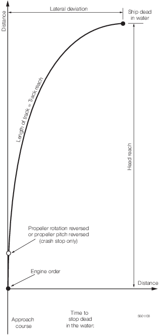
Figure 4.5.3 Presentation of both stopping trials' results
5.7.3 The
following information is to be derived from the trials data, see
Figure 4.5.4 Presentation of zig-zag manoeuvring trial results:
-
A plot of the
time histories of the rudder angles and corresponding ship’s
heading.
-
First overshoot
angle.
-
Second overshoot
angle.
-
Time to check
yaw (rate of change of heading equals zero) at each rudder reversal.
-
Initial turning
time.
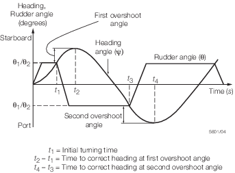
Figure 4.5.4 Presentation of zig-zag manoeuvring trial results
5.8 Initial turning manoeuvring trials
5.8.1 The
initial turning manoeuvring trial measures the transient effectiveness
of the rudder(s). To ascertain the ship’s initial turning ability,
in accordance with Vol 3, Pt 1, Ch 4, 4.4 Approach conditions, the
following data is to be recorded from the 10º/10º zig-zag
manoeuvring trials:
When the ship’s head has moved 10º off the base course,
after the initial rudder command, the number of ship lengths travelled
is to be recorded.
5.9 Spiral manoeuvring trials
5.9.1 This
trial measures the ship’s steady state rate of turn as a function
of the applied rudder angle, providing a qualitative measure of the
ship’s dynamic stability.
5.9.2 There
are two possible variations of the manoeuvring trials that can be
used to assess the ship’s dynamic stability, namely:
The direct, or Dieudonne, spiral manoeuvre.
The
reverse, or Bech, spiral manoeuvre.
5.9.3 The
direct spiral manoeuvre will yield more information about the degree
of instability. However, this manoeuvre is very time-consuming, requires
good weather conditions and, for larger ships, needs considerable
sea room. The reverse spiral manoeuvre provides a procedure for defining
the instability loop more rapidly than the direct spiral manoeuvre.
However, this trial requires accurate rudder angle and rate of turn
indicators. Where the ship is to be steered manually, the helmsman
is to be able to read the rate of turn indicator.
5.9.4 The
direct spiral manoeuvre is to be conducted as follows:
-
It is to be initiated
when:
-
the approach
conditions defined in Vol 3, Pt 1, Ch 4, 4.4 Approach conditions have
been satisfied, and
-
the rudder
is ordered to 25º to starboard.
-
It must continue
without any alteration to the engine control settings.
-
The rudder is
to be held until the indicated rate of turn is assumed constant.
-
The rudder angle
is then to be decreased by 5º and held until the rate of turn
is assumed constant.
-
The manoeuvre
is to be terminated when the rudder has moved through the range of
25º to starboard to 25º to port and then back to 25º
to starboard in incremental rudder angles of 5º.
-
For dynamically
unstable ships, the incremental rudder angle in the range of 10º
to starboard through to 10º to port is to be 2º.
5.9.5 The
reverse spiral manoeuvre is to be conducted as follows:
-
It
is to be initiated when:
-
the approach
conditions defined in Vol 3, Pt 1, Ch 4, 4.4 Approach conditions have
been satisfied; and
-
the first
constant rate of change of heading is achieved.
-
It must continue
without any alteration to the engine control settings.
-
The recommended
constant rates of turn are defined as percentages of the steady state
rate of turn, r, derived from the turning circle, as
shown in Table 4.5.2 Recommended constant rate of change of heading. For
the LNMA notation specific constant rates of turn may
be specified.
-
The points P1
to P8 represent positions on the spiral curve, see
Figure 4.5.5 Presentation of spiral manoeuvring trial results for a dynamically unstable ship.
-
The first and
last points on the spiral curves (P1 and P8) can be derived from the
turning circle manoeuvres.
-
The ship is to
be steered at a constant rate of turn and the mean rudder angle to
achieve the desired rate of turn is to be noted. The rudder angle
deviations are not to be greater than ± 2º.
-
The manoeuvre
is to be terminated when all points have been determined.
Table 4.5.2 Recommended constant rate of change of heading
| Points
|
Rate of change of heading
|
| P1 and P8
|
1,0 r
|
| P2 and P7
|
0,6 r
|
| P3 and P6
|
0,3 r
|
| P4 and P5
|
0,1 r
|
where r = change of heading per second = 
|
5.10 Man overboard manoeuvring trials
5.10.1 The
man overboard manoeuvre provides the Master with important information
on the time taken and the deviation from course necessary to retrieve
a person or object from the sea. The elliptical and Williamson turns
are two well-known man overboard manoeuvres. These manoeuvres will,
in the absence of wind and current, bring the ship back to the position
where the man overboard incident occurred.
5.10.2 The
elliptical turning manoeuvre is to be conducted as follows:
-
It
is to be initiated when:
-
the approach
conditions defined in Vol 3, Pt 1, Ch 4, 4.4 Approach conditions have
been satisfied, and
-
the rudder
is ordered hard over.
-
It must continue
without any alteration to the engine control settings.
-
The rudder is
to remain hard over until the ship has altered course by 180º.
The ship is to be steadied on the reciprocal heading until the approach
speed has been regained.
-
The rudder is
once again placed hard over and the ship is steadied on the original
course.
-
This manoeuvre
is to be terminated when the ship has returned to the position, or
nearest position, where the manoeuvre was initiated.
5.10.3 The
Williamson turning manoeuvre is considered quicker than the elliptical
turning manoeuvre in returning the ship to the original man overboard
position. This manoeuvre is to be conducted as follows:
-
It
is to be initiated when:
-
the approach
conditions defined in Vol 3, Pt 1, Ch 4, 4.4 Approach conditions have
been satisfied, and
-
the rudder
is ordered hard over.
-
It must continue
without any alteration to the engine control settings.
-
The rudder is
to remain hard over until the ship has altered course by 70º.
The rudder is then ordered hard over to the opposite side, until the
ship is on a course which is the reciprocal of the original approach
course.
-
It is terminated
when the ship has returned to the position, or nearest position, where
the manoeuvre was initiated.
5.10.4 The
following information is to be derived from the trials data, see
Figure 4.5.6 Presentation of the Williamson turn, man overboard, manoeuvring trial results:
-
A plot of the
ship’s track.
-
The time taken
to return to the point, or nearest position to that point, at which
the manoeuvre was initiated.
-
The lateral deviation
from the initial course at the point, or nearest position to that
point, at which the manoeuvre was initiated.
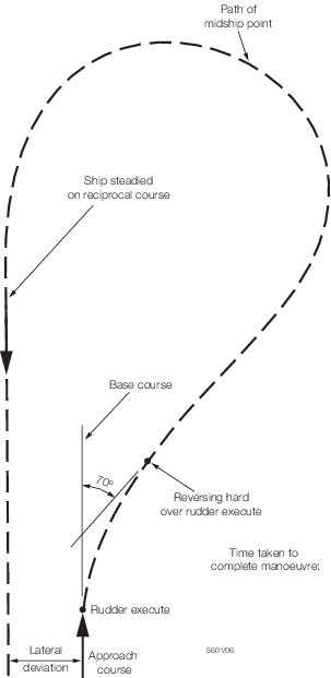
Figure 4.5.6 Presentation of the Williamson turn, man overboard, manoeuvring trial results
5.11 Manoeuvring trials for auxiliary thrusters
5.11.1 Where
a ship is fitted with auxiliary thrusters, such as bow thrusters,
a turning circle manoeuvre is required to be performed to determine
the effectiveness of those thrusters in turning the ship through 180º.
This trial is to be carried out with the wind initially from the stern
and the ship turning into the wind.
5.11.2 The
auxiliary thrusters’ turning circle is to be conducted as follows:
-
All primary thrusters
stopped and the ship dead in the water.
-
The ship is to
be completely stopped in the water with head to wind.
-
The auxiliary
thrusters are to be set to maximum power to turn the ship.
-
The manoeuvring
trial is to be completed when the ship has turned through 180º.
5.11.4 If required by Vol 3, Pt 1, Ch 4, 3.2 Verification requirements 3.2.6 (LNMA notation only) a self berthing
manoeuvre is to be carried out:
-
The ship is to
be positioned bow or stern to the wind.
-
All primary thrusters
stopped and the ship dead in the water.
-
The auxiliary
thrusters are to be set to maximum power for transverse motion.
-
The manoeuvre
may be terminated when the ship has recorded a steady transverse speed
with zero rate of rotation.
5.11.5 The
following information is to be derived from the trials data:
-
The time taken
to reach a steady transverse velocity.
-
The maximum transverse
velocity attained.
-
The heading of
the vessel at least every two seconds during the manoeuvre.
5.12 Acceleration trials
5.12.1 The
acceleration trials information on the distance and time to achieve
a speed defined by 80–100 per cent MCR set speeds from a dead
stop.
5.12.2 The
following trial procedure is to be followed as illustrated in Figure 4.5.7 Acceleration trial:
-
Establish a steady
ship speed in accordance with the trial agenda and adjust the ship’s
heading to a steady course. At a position roughly one ship length
before the point where the engine order is initiated, start the acquisition
system.
-
Execute the prescribed
engine order.
-
The rudder is
to be used to a minimal extent and only to keep the ship on course.
-
When the ship
attains the steady terminal speed stated in the trial agenda, the
test is complete.
5.12.3 The
following information is to be derived from the trials data:
-
The time taken
to reach the terminal speed specified in the trials agenda.
-
The distance
covered from the time the engine order is initiated until the ship
reaches the terminal speed specified in the trials agenda.
-
Lateral deviation
and final heading.
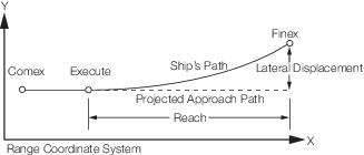
Figure 4.5.7 Acceleration trial
5.13 Turning from rest
5.13.1 The
turning from rest manoeuvre is to be conducted as follows:
-
All primary and
auxiliary thrusters are stopped and the ship dead in the water;
-
the rudder is
ordered hard over;
-
the demand for
full ahead power is given from the engine control position on the
bridge;
-
the ship must
continue without any alteration to the engine control settings;
-
the rudder is
to remain hard over until the ship has altered course by 90°;
-
this manoeuvre
is to be terminated when the ship has altered course by 90°.
5.13.2 The
time taken from the full ahead order until the ship has altered course
by 90° is to be recorded.
|