
Section
9 Flat surfaces and flat tube plates
9.1 Stayed flat surfaces
9.1.1 Where
flat end plates are flanged for connection to the shell, the inside
radius of flanging is to be not less than 1,75 times the thickness
of the plate, with a minimum of 38 mm.
9.1.2 Where
combustion chamber or firebox plates are flanged for connection to
the wrapper plate, the inside radius of flanging is to be equal to
the thickness of the plate, with a minimum of 25 mm.
9.1.3 Where
unflanged flat plates are connected to the shell by welding, typical
methods of attachment are shown in Figure 1.9.1 Typical attachment of unflanged flat end plates to shell . Similar forms of attachment may be used where unflanged
combustion chamber or firebox plates are connected to the wrapper
plate by welding.
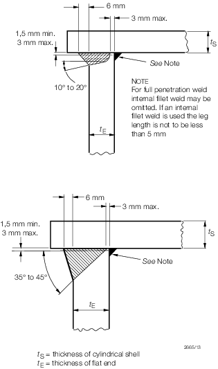
Figure 1.9.1 Typical attachment of unflanged flat end plates to shell
9.1.4 Where
the flange curvature is a point of support, this is to be taken at
the commencement of curvature, or at a line distant 3,5 times the
thickness of the plate from the outside of the plate, whichever is
nearer to the flange.
9.1.5 Where
a flat plate is welded directly to a shell or wrapper plate, the point
of support is to be taken at the inside of the shell or wrapper plate.
9.1.6 The
thickness, t, of those portions of flat plates supported
by stays and around tube nests is to be determined by the following
formula:
where t, p, c and σ are as defined in Vol 2, Pt 8, Ch 1, 1.2 Definition of symbols
|
d
|
= |
diameter
of the largest circle which can be drawn through at least three points
of support. At least one point of support must lie on one side of
any diameter of the circle. |
9.1.7 The
value of C in the formula in Vol 2, Pt 8, Ch 1, 9.1 Stayed flat surfaces 9.1.6 is to be as follows:
-
Where plain bar
stays are strength welded into the plates as shown in Figure 1.9.2 Typical attachment of firebox, combustion chamber stays and bar stays
-
Where plain bar
stays pass through holes in the plates and are fitted on the outside
with washers as shown in Figure 1.9.3 Typical attachment of bar stays
|
C
|
= |
0,12
where the diameter of the washer is 3,5 times the diameter of the
stay |
|
C
|
= |
0,113
where the diameter of the washer is 0,67 times the pitch of the stays. |
-
Where the flat
plate is flanged for attachment to the shell, flue, furnace or wrapper
or, alternatively, is welded directly to shell, flue, furnace or wrapper, see
Vol 2, Pt 8, Ch 1, 9.1 Stayed flat surfaces 9.1.4 and Vol 2, Pt 8, Ch 1, 9.1 Stayed flat surfaces 9.1.5:
-
Where the support
is a gusset stay
-
Where the support
is a tube secured as shown in Figure 1.9.4 Detail of weld for tube
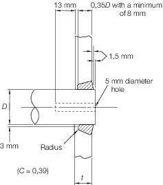
Figure 1.9.2 Typical attachment of firebox, combustion chamber stays and bar stays
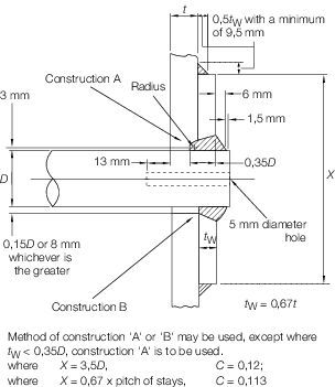
Figure 1.9.3 Typical attachment of bar stays
9.1.9 In the
case of small boilers with a single tube nest of expanded tubes which
does not exceed an area of 0,65 m2, welded tubes need not
be fitted provided the tubes are beaded at the inlet end. In this
instance the support afforded by the expanded tubes is not to be taken
to extend beyond the line enclosing the outer surfaces of the tubes
except that, between the outside of the nest and the attachment of
the end plate to shell, there may be an unsupported width equal to
the flat plate margin, as given by the formula in Vol 2, Pt 8, Ch 1, 9.4 Flat plate margins 9.4.1. The required tube plate thickness
within such a tube nest is to be determined using the formula in Vol 2, Pt 8, Ch 1, 9.1 Stayed flat surfaces 9.1.6, where:
|
d
|
= |
four
times the mean pitch, in mm, of the expanded tubes in the nest. |
9.1.10 The
thickness, t, of any tube plate in the tube area is to
be not less than that required for the surrounding plate determined
by Vol 2, Pt 8, Ch 1, 9.1 Stayed flat surfaces 9.1.6 and in no case less
than:
-
12,5 mm where
the diameter of the tube hole does not exceed 50 mm, or
-
14 mm where the
diameter of the tube hole is greater than 50 mm.
9.1.11 Alternative
methods of support will be specially considered.
9.1.12 The
spacing of tube holes is to be such that the minimum width, b,
in mm of any ligament between tube holes is not less than:
for expanded tubes:
for welded tubes:
where
|
d
|
= |
diameter
of the hole drilled in the plate, in mm. |
9.1.13 Where
a flat plate has a manhole or sight hole and the opening is strengthened
by flanging, the total depth, H, of the flange, measured
from the outer surface of the plate, is to be not less than:
where
|
t
|
= |
thickness
of plate, in mm |
|
H
|
= |
depth
of flange, in mm |
|
W
|
= |
minor
axis of manhole or sight hole, in mm. |
9.1.14 Where
the flat top plates of combustion chambers are supported by welded-on
girders, the equation in Vol 2, Pt 8, Ch 1, 9.1 Stayed flat surfaces 9.1.6 is
to apply as follows:
-
In the case of
welded-on girders provided with waterways
|
d
|
= |

|
where
|
X
|
= |
width
of waterway in the girder plus the thickness of the girder, in mm |
|
Y
|
= |
pitch
of girders, in mm. |
-
In the case of
continuously welded-on girders
where
|
D
|
= |
distance
between inside faces of girders, in mm. |
9.2 Combustion chamber tube plates under compression
9.2.1 The
thickness of combustion chamber tube plates under compression due
to the pressure on the top plate, based on a compressive stress not
exceeding 96 N/mm2 is to be determined by the following
formula:
where t and p are as defined
in Vol 2, Pt 8, Ch 1, 1.2 Definition of symbols
|
d
|
= |
internal
diameter of the plain tubes, in mm |
|
s
|
= |
pitch
of tubes, in mm, measured horizontally where tubes are chain pitched,
or diagonally where the tubes are staggered pitched and the diagonal
pitch is less than the horizontal pitch |
|
W
|
= |
internal
width of the combustion chamber, in mm, measured from tube plate to
back chamber plate. |
9.3 Girders for combustion chamber top plates
9.3.1 The
formula in 9.3.2 is applicable to plate girders welded to the top
combustion chamber plate by means of a full penetration weld.
9.3.2 The
thickness of steel plate girders supporting the tops of combustion
chambers is to be determined by the following formula:
where t and p are as defined
in Vol 2, Pt 8, Ch 1, 1.2 Definition of symbols
|
d
|
= |
effective
depth of girder, in mm |
|
l
|
= |
length
of girder measured internally from tube plate to back chamber plate,
in mm |
|
s
|
= |
pitch
of the girders, in mm |
|
R
20
|
= |
specified minimum tensile strength of the girder plate, in N/mm2.
|
9.4 Flat plate margins
9.4.1 The
width of margin, b, of a flat plate which may be regarded
as being supported by the shell, furnaces or flues to which the flat
plate is attached is not to exceed that determined by the following
formula:
where p, c and σ are as defined in Vol 2, Pt 8, Ch 1, 1.2 Definition of symbols
|
t
|
= |
thickness
of the flat plate, in mm |
|
b
|
= |
width
of margin, in mm |
9.4.2 Where
an unflanged flat plate is welded directly to the shell, furnaces
or flues and it is not practicable to effect the full penetration
weld from both sides of the flat plate, the constant C used
in the formula in Vol 2, Pt 8, Ch 1, 9.4 Flat plate margins 9.4.1 is
to be:
9.4.3 In the
case of plates which are flanged, the margin is to be measured from
the commencement of curvature of flanging, or from a line 3,5 times
the thickness of the plate measured from the outside of the plate,
whichever is nearer to the flange.
9.4.4 Where
the flat plate is not flanged for attachment to the shell, furnaces
or flues, the margin is to be measured from inside of the shell or
the outside of the furnaces or flues, whichever is applicable.
9.4.5 In no
case is the diameter D, in mm, of the circle forming
the boundary of the margin supported by the uptake of a vertical boiler
to be greater than determined by the following formula:
where p is as defined in Vol 2, Pt 8, Ch 1, 1.2 Definition of symbols
|
d
|
= |
external
diameter of uptake, in mm |
|
d
i
|
= |
internal diameter of uptake, in mm |
|
A
|
= |
cross-sectional
area of the uptake tube material, |
|