
Section
11 Furnaces subject to external pressure
11.1 Maximum thickness
11.1.1 Furnaces,
plain or corrugated, are not to exceed 22,5 mm in thickness.
11.2 Corrugated furnaces
11.2.1 The
minimum thickness, t, of corrugated furnaces is to be
determined by the following formula:
where p and c are defined in Vol 2, Pt 8, Ch 1, 1.2 Definition of symbols
|
t
|
= |
thickness
of the furnace plate measured at the bottom of the corrugations, in
mm |
|
C
|
= |
1060
for Fox, Morison and Deighton corrugations |
| = |
1130 for Suspension Bulb corrugations |
|
D
o
|
= |
external diameter of the furnace measured at the bottom of the
corrugations, in mm. |
11.3 Plain furnaces, flue sections and combustion chamber bottoms
11.3.1 The
minimum thickness, t, between points of substantial support,
of plain furnaces or furnaces strengthened by stiffening rings, of
flue sections and of the cylindrical bottoms of combustion chambers
is to be determined by the following formulae, the greater of the
two thicknesses obtained being taken:
where t, c and p are as defined in Vol 2, Pt 8, Ch 1, 1.2 Definition of symbols
|
C
|
= |
 or 0,85 whichever is the greater or 0,85 whichever is the greater
|
|
D
o
|
= |
external diameter of the furnace, flue or combustion chamber,
in mm |
|
L
|
= |
length
of section between the centres of points of substantial support, in
mm |
x and σ are as defined in Vol 2, Pt 8, Ch 1, 11.7 Dished and flanged ends for unsupported vertical boiler furnaces 11.7.1.
11.3.2 Where
stiffeners are used for strengthening plain cylindrical furnaces,
or combustion chambers, the second moment of area, I,
of the stiffener is to be determined by the following formula:
where p is as defined in Vol 2, Pt 8, Ch 1, 1.2 Definition of symbols
|
D
o
|
= |
external diameter of the furnace flue or combustion chamber,
in mm |
|
L
|
= |
length
of section between the centres of points of substantial support, in
mm |
For proportion of stiffening rings, see
Figure 1.11.1 Furnace, flue and combustion chamber stiffeners.
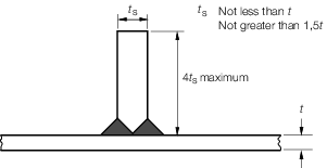
Figure 1.11.1 Furnace, flue and combustion chamber stiffeners
11.4 Plain furnaces of vertical boilers
11.4.1 The
thickness of plain furnaces not exceeding 2000 mm in external diameter
is to be determined by the formulae given in Vol 2, Pt 8, Ch 1, 11.3 Plain furnaces, flue sections and combustion chamber bottoms 11.3.1, the greater of the two
thicknesses being taken:
where
|
D
o
|
= |
external diameter of the furnace, in mm. Where the furnace is
tapered, the diameter to be taken for calculation purposes is to be
the mean of that at the top and that at the bottom where it meets
the substantial support from flange, ring or row of stays |
11.4.2 For
furnaces under 760 mm in external diameter, the thickness is to be
not less than 8 mm, and for furnaces 760 mm in external diameter and
over, the thickness is to be not less than 9,5 mm.
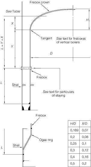
Figure 1.11.2 Effective length, L, for use in 11.4
11.4.3 A
circumferential row of stays connecting the furnace to the shell will
be considered to provide substantial support to the furnace, provided
that:
- The diameter of the stay is not less than 22,5 mm or twice the
thickness of the furnace, whichever is the greater.
- The pitch of the stays at the furnace does not exceed 14 times
the thickness of the furnace.
11.5 Hemispherical furnaces
11.5.1 The
minimum thickness, t, of unsupported hemispherical furnaces
subject to pressure on the convex surface is to be determined by the
following formula:
|
t
|
= |
 + c + c
|
where t, c and p are as defined in Vol 2, Pt 8, Ch 1, 1.2 Definition of symbols
x and
σ are as defined in Vol 2, Pt 8, Ch 1, 11.7 Dished and flanged ends for unsupported vertical boiler furnaces 11.7.1
|
C
|
= |
 or 0,85, whichever is the greater or 0,85, whichever is the greater
|
|
R
o
|
= |
outer radius of curvature of the furnace, in mm. |
11.5.2 In no case is the maximum thickness to exceed 22,5 mm, or the ratio  to exceed 100. to exceed 100.
11.6 Dished and flanged ends for supported vertical boiler furnaces
11.6.1 The
minimum thickness, t, of dished and flanged ends for
vertical boiler furnaces that are subject to pressure on the convex
side and are supported by central uptakes, is to be determined by
the following formula:
where t, c, p, Ro and σ are as
defined in Vol 2, Pt 8, Ch 1, 1.2 Definition of symbols
11.7 Dished and flanged ends for unsupported vertical boiler furnaces
11.7.1 The
minimum thickness, t, of dished and flanged ends for
vertical boiler furnaces that are subject to pressure on the convex
side and are without support from stays of any kind, is to be determined
by the following formula, but is in no case to be less than the thickness
of the firebox:
where t, c and p are as defined in Vol 2, Pt 8, Ch 1, 1.2 Definition of symbols
|
x
|
= |
specified
minimum lower yield stress or 0,2 per cent proof stress in N/mm2 at
a temperature 90°C above the saturated steam temperature corresponding
to the design pressure for carbon and carbon manganese steel with
a specified minimum tensile strength of 400 N/mm2
|
|
C
|
= |
 or 0,85 whichever is the greater or 0,85 whichever is the greater
|
|
R
o
|
= |
outside radius of the crown plate, in mm |
| = |

|
|
σ |
= |
specified
minimum lower yield stress or 0,2 per cent proof stress in N/mm2 at
a temperature 90°C above the saturated steam temperature corresponding
to the design pressure for the steel actually used.
|
11.7.2 The
inside radius of curvature, R
i, of the end
plate is to be not greater than the external diameter of the cylinder
to which it is attached.
11.7.3 The
inside knuckle radius, r
i, see
Figure 1.4.2 Typical dished ends(a), of the arc joining
the cylindrical flange to the spherical surface of the end is to be
not less than four times the thickness of the end plate and in no
case less than 65 mm.
11.8 Ogee rings
11.8.1 The
minimum thickness, t, of the ogee ring which connects
the bottom of the furnace to the shell of a vertical boiler and sustains
the whole vertical load on the furnace is to be determined by the
following formula:
where t, c and p are as defined in Vol 2, Pt 8, Ch 1, 1.2 Definition of symbols
|
D
i
|
= |
inside diameter of boiler shell, in mm |
|
D
o
|
= |
outside diameter of the lower part of the furnace where it joins
the ogee ring, in mm. |
11.8.2 Proposals
to use a flat plate annular ring which connects the bottom of the
furnace to the shell of a vertical boiler and sustains any unbalanced
vertical load on the furnace will be the subject of special consideration.
11.9 Uptakes of vertical boilers
11.9.1 The
minimum thickness, t, of internal uptakes of vertical
boilers is to be determined by the following formulae, the greater
of the two thicknesses obtained being taken:
where t and p are as defined
in Vol 2, Pt 8, Ch 1, 1.2 Definition of symbols
|
D
o
|
= |
external diameter of uptake, in mm |
|
L
|
= |
length
of uptake between the centres of points of substantial support, in
mm. |
|