
Section
5 Pipe joints
5.1 General
5.1.1 Connections
in piping systems may be made by any of the methods described in this
Section, or by special types of approved joints which have been shown
to be suitable for the design conditions. Details of connection methods,
not described in this Section are to be submitted for consideration.
5.1.2 The
selection of pipe connections in piping systems is to recognise the
boundary fluids, pressure and temperature conditions, external or
cyclic loading and location.
5.1.3 Pipe
connections in accordance with national or other established standards
will be accepted where the standards are appropriate to the piping
system.
5.1.4 The
type and location of pipe connections are to recognise the need to
facilitate Periodic Survey of piping systems and associated items
of machinery and the need for cold ‘pull up’ if required.
5.1.5 Pipe
connections are not to be used to compensate for pipe misalignment.
5.1.6 Piping
with joints is to be adequately adjusted, aligned and supported. Supports
or hangers are not to be used to force alignment of piping at the
point of connection.
5.1.7 Pipes
passing through, or connected to, watertight decks are to be continuous
or provided with an approved bolted or welded connection to the deck
or bulkhead.
5.2 Flange connections
5.2.1 The dimensions and configuration of flanges and bolting are to be selected
in accordance with recognised standards. The dimensions and bolting arrangements of
nonstandard flanges will be the subject of special consideration.
5.2.2 Gaskets are to be suitable for the conveyed fluids under design pressure
and temperature conditions and their dimensions and configuration is to be in accordance
with recognised standards. Gasket materials used in oil piping systems are to be
impervious to oil and the thinnest possible as determined from manufacturer's
recommendations that the flange arrangement will allow, to ensure the minimum loss of
bolt stress due to gasket relaxation.
5.2.3 Flange connections having components sensitive to heat, including gaskets or isolation
kits, are not to be used in spaces where leakage or failure caused by fire could result
in fire spread, flooding or loss of a Mobility or Ship Type system.
5.2.4 Acceptable flange pipe connections are indicated in Figure 1.5.1 Typical welded-on flanges. Limiting applications of different types of
flange connections are indicated in Table 1.5.1 Limiting design conditions for
flange types depending on the size, pressure and
temperature.
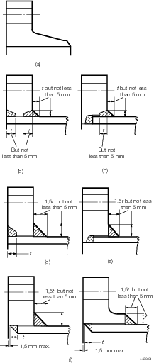
Figure 1.5.1 Typical welded-on flanges
Table 1.5.1 Limiting design conditions for
flange types
| Flangetype
|
Maximumpressure
|
Maximumtemperature
|
Maximumpipe o.d.
|
Maximumpipe bore
|
|
|
|
°C
|
mm
|
mm
|
| (a)
|
Pressure-temperature ratings to be in accordance with a recognised
standard
|
No
restriction
|
No
restriction
|
No
restriction
|
| (b)
|
Pressure-temperature ratings to be in accordance with a recognised
standard
|
No
restriction
|
168,3
foralloy steels*
|
No
restriction
|
| (c)
|
Pressure-temperature ratings to be in accordance with a recognised
standard
|
No
restriction
|
168,3
foralloy steels*
|
75
|
| (d)
|
Pressure-temperature ratings to be in accordance with a recognised
standard
|
425
|
No
restriction
|
No
restriction
|
| (e)
|
Pressure-temperature ratings to be in accordance with a recognised
standard
|
425
|
No
restriction
|
75
|
| (f)
|
Pressure-temperature ratings to be in accordance with a recognised
standard
|
425
|
No
restriction
|
No
restriction
|
| * No restriction for carbon steels
|
5.3 Screwed-on flanges
5.3.1 Where
flanges are secured by screwing, as indicated in Figure 1.5.2 Screwed on flange, the pipe and flange
are to be screwed with a vanishing thread and the diameter of the
screwed portion of the pipe over the thread is not to be appreciably
less than the outside diameter of the unscrewed pipe. After the flange
has been screwed hard home the pipe is to be expanded into the flange.
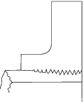
Figure 1.5.2 Screwed on flange
5.3.2 The
vanishing thread on a pipe is to be not less than three pitches in
length, and the diameter at the root of the thread is to increase
uniformly from the standard root diameter to the diameter at the top
of the thread. This may be produced by suitably grinding the dies,
and the flange should be tapered out to the same formation.
5.3.3 Such
screwed and expanded flanges may be used for steam for a maximum design
pressure of 30 bar and maximum design temperature of 370°C and
for feed for maximum design pressure of 50 bar.
5.4 Welded-on flanges, butt welded joints and fabricated branch pieces
5.4.1 The
types of welded-on flanges are to be suitable for the pressure, temperature
and service for which the pipes are intended.
5.4.3 Welded-on
flanges are not to be a tight fit on the pipes. The maximum clearance
between the bore of the flange and the outside diameter of the pipe
is to be 3 mm at any point, and the sum of the clearances diametrically
opposite is not to exceed 5 mm.
5.4.4 Where
butt welds are employed in the attachment of flange type (a), in pipe-to-pipe
joints or in the construction of branch pieces, the adjacent pieces
are to be matched at the bores. This may be effected by drifting,
roller expanding or machining, provided that the pipe wall is not
reduced below the designed thickness. If the parts to be joined differ
in wall thickness, the thicker wall is to be gradually tapered to
the thickness of the thinner at the butt joint. The welding necks
of valve chests are to be sufficiently long to ensure that the valves
are not distorted as the result of welding and subsequent heat treatment
of the joints.
5.4.5 Where
backing rings are used with flange type (a) they are to fit closely
to the bore of the pipe and should be removed after welding. The rings
are to be made of the same material as the pipes or of mild steel
having a sulphur content not greater than 0,05 per cent.
5.4.6 Branches
may be attached to pressure pipes by means of welding provided that
the pipe is reinforced at the branch by a compensating plate or collar
or other approved means, or alternatively that the thickness of pipe
and branch are increased to maintain the strength of the pipe. These
requirements also apply to fabricated branch pieces.
5.4.7 Welding
may be carried out by means of the shielded metal arc, inert gas metal
arc, oxy-acetylene or other approved process, but, in general, oxy-acetylene
welding is suitable only for flange type (a) and is not to be applied
to pipes exceeding 100 mm diameter or 9,5 mm thick. The welding is
to be carried out in accordance with the appropriate paragraphs of Vol 2, Pt 1, Ch 4 Requirements for Fusion Welding of Pressure Vessels and Piping.
5.5 Loose flanges
5.5.1 Loose
flange designs as shown in Figure 1.5.3 Loose flange arrangements may
be used provided they are in accordance with a recognised National
or International Standard.
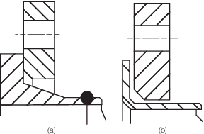
Figure 1.5.3 Loose flange arrangements
5.6 Socket weld joints
5.6.1 Socket
weld joints may be used in Class III systems with carbon steel pipes
of any outside diameter. Socket weld fittings are to be of forged
steel and the material is to be compatible with the associated piping.
In particular cases, socket weld joints may be permitted for piping
systems of Class I and II having outside diameter not exceeding 88,9
mm. Such joints are not to be used where fatigue, severe erosion or
crevice corrosion is expected to occur or where toxic or asphyxiating
media are conveyed, other than for carbon dioxide fire-extinguishing
distribution piping.
5.6.2 The
thickness of the socket weld fittings is to meet the requirements
of Vol 2, Pt 7, Ch 1, 6.1 Wrought steel pipes and bends 6.1.3, but is to be not
less than 1,25 times the nominal thickness of the pipe or tube. The
diametrical clearance between the outside diameter of the pipe and
the bore of the fitting is not to exceed 0,8 mm, and a gap of approximately
1,5 mm is to be provided between the end of the pipe and the bottom
of the socket.
5.6.3 The
leg lengths of the fillet weld connecting the pipe to the socket weld
fitting are to be such that the throat dimension of the weld is not
less than the nominal thickness of the pipe or tube.
5.7 Threaded sleeve joints
5.7.1 Threaded
sleeve joints, in accordance with national or other established standards,
may be used with carbon steel pipes within the limits given in Table 1.5.2 Limiting design conditions for
threaded sleeve joints. Such joints are not
to be used where fatigue, severe erosion or crevice corrosion is expected
to occur or where flammable or toxic media is conveyed.
Table 1.5.2 Limiting design conditions for
threaded sleeve joints
| Thread
type
|
Outside pipe diameter, in mm
|
| Class 1
|
Class II
|
Class III
|
| Tapered thread
|
<33,7
|
<60,3
|
<60,3
|
| Parallel thread
|
—
|
—
|
<60,3
|
5.8 Welded sleeve joints
5.8.1 Welded
sleeve joints may be used in Class III systems with carbon steel pipes
of any outside diameter. In particular cases, welded sleeve joints
may be permitted for piping systems of Class I and II having outside
diameter not exceeding 88,9 mm. Such joints are not to be used where
fatigue, severe erosion or crevice corrosion is expected to occur
or where toxic media are conveyed.
5.8.2 Welded
sleeve joints are not to be used in the following locations:
- Bilge pipes in way of deep tanks.
- Cargo oil piping outside of the cargo area for bow or stern loading/discharge.
- Air and sounding pipes passing through cargo tanks.
5.8.3 Welded
sleeve joints may be used in piping systems for the storage, distribution
and utilisation of fuel oil, lubricating or other flammable oil systems
in machinery spaces provided they are located in readily visible and
accessible positions. see also
Vol 2, Pt 7, Ch 3, 2.8 Temperature indication 2.8.2.
5.8.4 Welded
sleeve joints are not to be used at deck/bulkhead penetrations that
require continuous pipe lengths.
5.8.6 The
sleeve material is to be compatible with the associated piping and
the leg lengths of the fillet weld connecting the pipe to the sleeve
are to be such that the throat dimension of the weld is not less than
the nominal thickness of the pipe or tube.
5.8.7 The
minimum length of the sleeve is to conform to the following formula:
5.9 Screwed fittings
5.9.1 Screwed
fittings, including compression fittings, of an approved type may
be used in piping systems for pipes not exceeding 51 mm outside diameter.
Where the fittings are not in accordance with an acceptable standard
then LR may require the fittings to be subjected to special tests
to demonstrate their suitability for the intended service and working
conditions.
5.10 Other mechanical couplings
5.10.1 Pipe unions, compression couplings, or slip-on joints, as shown in Figure 1.5.4 Examples of mechanical joints
(Part 1) and Figure 1.5.5 Examples of mechanical joints
(Part 2), may be used if
type approved for the service conditions, the pipe material and the intended
application. The type approval is to be based on the results of testing of the actual
joints. The acceptable use for each service is indicated in Table 1.5.3 Application of mechanical
joints and dependence
upon the class of piping, with limiting pipe dimensions, working pressure and
temperature is indicated in Table 1.5.4 Application of mechanical joints
depending on class of piping.
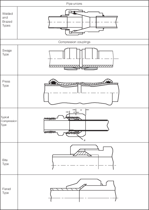
Figure 1.5.4 Examples of mechanical joints
(Part 1)
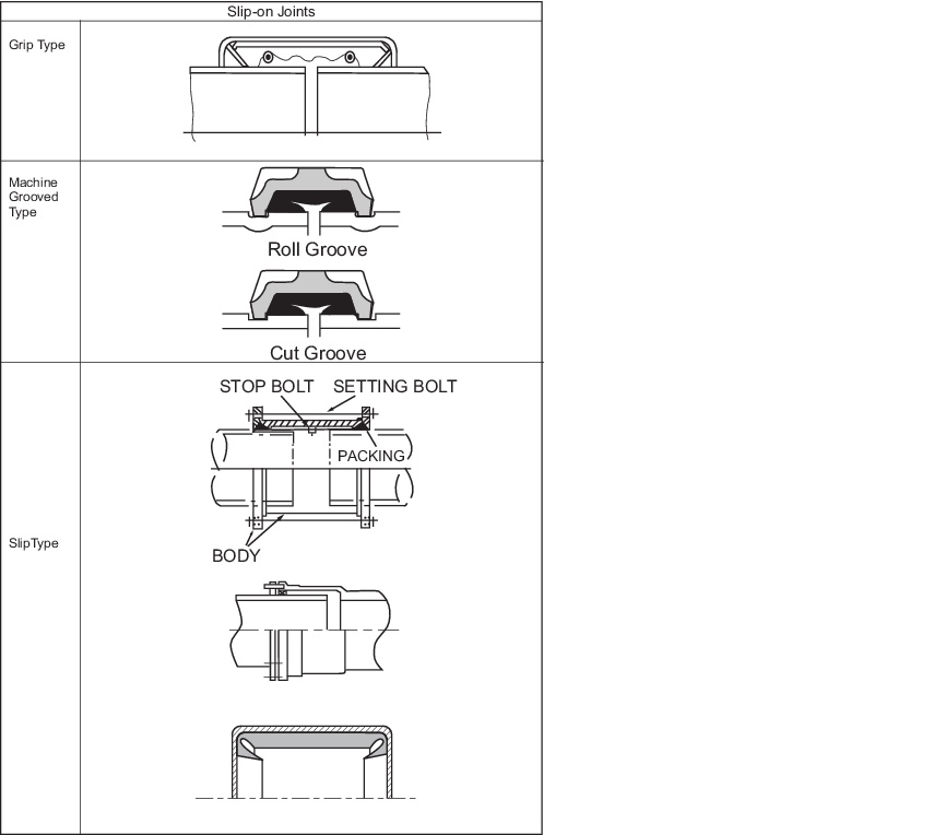
Figure 1.5.5 Examples of mechanical joints
(Part 2)
Table 1.5.3 Application of mechanical
joints
| Systems
|
Type of connections
|
| Pipe unions
|
Compression coupling
|
Slip-on joints
|
| Flammable
fluids (Flash point <60° C)
|
| Aircraft and vehicle fuel oil lines
see Notes 2 & 4
|
+
|
+
|
+
|
| Vent lines see Note 2 &
3
|
+
|
+
|
+
|
| Flammable
fluids (Flash point > 60° C)
|
| Aircraft and vehicle fuel oil lines
see Note 2 & 4
|
+
|
+
|
+
|
| Ship’s machinery fuel oil lines
see Notes 2 & 3
|
+
|
+
|
+
|
| Lubricating oil lines see
Notes 2 & 3
|
+
|
+
|
+
|
| Hydraulic oil see Notes 2
& 3
|
+
|
+
|
+
|
| Thermal oil see Notes 2 &
3
|
+
|
+
|
+
|
| Sea
water
|
| Bilge lines see Note 1
|
+
|
+
|
+
|
| HP sea-water and water spray (not
permanently filled) see Note 3
|
+
|
+
|
+
|
| Water filled fire-extinguishing
systems, e.g. sprinkler systems see Note 3
|
+
|
+
|
+
|
| Non-water filled fire-extinguishing
systems, e.g. foam, drencher systems see Note 3
|
+
|
+
|
+
|
| Ballast system see Note
1
|
+
|
+
|
+
|
| Cooling water system see Note
1
|
+
|
+
|
+
|
| Tank cleaning services
|
+
|
+
|
+
|
| Non-essential systems
|
+
|
+
|
+
|
| Fresh
water
|
| Cooling water system see Note
1
|
+
|
+
|
+
|
| Chilled water systems see Note
1
|
+
|
+
|
+
|
| Condensate return see Note
1
|
+
|
+
|
+
|
| Made water and demineralised water
system
|
+
|
+
|
+
|
| Ancillary system
|
+
|
+
|
+
|
| Sanitary/Drains/Scuppers
|
| Deck drains (internal) see
Note 6
|
+
|
+
|
+
|
| Sanitary drains
|
+
|
+
|
+
|
| Scuppers and discharge (overboard)
|
+
|
+
|
-
|
| Sounding
/Vent
|
| Water tanks/Dry spaces
|
+
|
+
|
+
|
| Oil tanks (f.p.>60° C) see
Notes 2 & 3
|
+
|
+
|
+
|
| Intakes and uptakes see Note
7
|
|
|
|
| HVAC trunking see Note 7
|
|
|
|
| Miscellaneous
|
| High pressure (HP) air systems
see Note 1
|
+
|
+
|

|
| Medium pressure (MP) air systems
(Starting air) see Note 1
|
+
|
+
|

|
| Low pressure (LP) air systems (incl.
Control air) see Note 1
|
+
|
+
|

|
| Service air (non-essential)
|
+
|
+
|
+
|
| Brine
|
+
|
+
|
+
|
| CO2 system see Note
1
|
+
|
+
|

|
| Nitrogen system
|
+
|
+
|

|
| Steam
|
+
|
+
|
see Note 5
|
| KEY
|
| +
|
Application is allowed
|
|
|

|
Application is not allowed
|
|
|
Note
1. Mechanical joints that include any
components which readily deteriorate in case of fire, are to be of an
approved fire-resistant type when fitted in machinery spaces of
category A. Mechanical couplings fitted on the ‘bilge main’ in
machinery spaces of category A are to be of steel, CuNi or equivalent
material.
|
Note
2. Slip-on joints are not accepted
inside machinery spaces of category A, munition stores, or
accommodation spaces. Slip-on joints are accepted in other machinery
and service spaces provided that the joints are located in easily
visible and accessible positions.
|
Note
3. Mechanical joints are to be of an
approved fire-resistant type, except when they are fitted on open
decks having little or no fire risk as defined in SOLAS Chapter II-2,
Regulation 9.2.3.3.2.2(10).
|
Note
4. Mechanical joints are to be of an
approved fire-resistant type
|
|
|
Note
6. Mechanical joints are only permitted
above the limit of watertight integrity.
|
Note
7. Requirements for HVAC trunking or gas
turbine updates and intakes are addressed in the relevant Sections of
the Rules.
|
Table 1.5.4 Application of mechanical joints
depending on class of piping
| Types of
joints
|
Classes of piping systems
|
| Class I
|
Class II
|
Class III
|
| Pipe unions
|
|
|
|
| Welded and brazed type
|
+ (OD ≤ 60,3 mm)
|
+ (OD ≤ 60,3 mm)
|
+
|
| Compression couplings
|
|
|
|
| Swage type
|
-
|
-
|
+
|
| Bite type
|
+ (OD ≤ 60,3 mm)
|
+ (OD ≤ 60,3 mm)
|
+
|
| Typical compression type
|
+ (OD ≤ 60,3 mm)
|
+ (OD ≤ 60,3 mm)
|
+
|
| Flared type
|
+ (OD ≤ 60,3 mm)
|
+ (OD ≤ 60,3 mm)
|
+
|
| Press type
|
-
|
-
|
+
|
|
Slip-on joints
|
|
|
|
| Machine grooved type
|
+
|
+
|
+
|
| Grip type
|
-
|
+
|
+
|
| Slip type
|
-
|
+
|
+
|
| KEY
+
Application is allowed
- Application is not allowed
|
5.10.2 Where the application of mechanical joints results in a reduction in pipe
wall thickness due to the use of bite type rings or other structural elements, this is
to be taken into account in determining the minimum wall thickness of the pipe to
withstand the design pressure.
5.10.3 Materials of mechanical joints are to be compatible with the piping
material and internal and external media.
5.10.4 Mechanical joints for pressure pipes are to be tested to a burst pressure of
4 times the design pressure. For design pressures above 200 bar the required burst
pressure will be specially considered.
5.10.5 Mechanical joints, which in the event of damage could cause fire or
flooding, are not to be used in piping sections directly connected to the ship’s side
below the limit of watertight integrity or tanks containing flammable fluids.
5.10.6 The mechanical joints are to be designed to withstand internal and external
pressure as applicable and where used in suction lines are to be capable of operating
under vacuum.
5.10.7 The number of mechanical joints in flammable fluid systems is to be kept to
a minimum. In general, flanged joints are to conform to a recognised standard.
5.10.8 Generally, slip-on joints are not to be used in pipelines in cargo holds,
tanks, and other spaces which are not easily accessible. Application of these joints
inside tanks may only be accepted where the medium conveyed is the same as that in the
tanks.
5.10.9 Usage of slip type slip-on joints as the main means of pipe connection is
not permitted except for cases where compensation of axial pipe deformation is
necessary.
5.10.10 Restrained slip-on joints are permitted in steam pipes with a design
pressure of 10 bar or less on the weather decks of oil and chemical tankers to
accommodate axial pipe movement, see
Vol 2, Pt 7, Ch 2, 2.7 Provision for expansion.
5.10.11 Mechanical joints are to be tested in accordance with the test requirements
in LR’s Type Approval Test Specification Number 2, as relevant to the service conditions
and the intended application. The programme of testing is to be agreed with LR.
5.10.12 The type or location of pipe joints may be limited by the shock policy requirements
defined by the Naval Administration. The use of mechanical joints is to be considered
against the shock requirements.
5.11 Additional requirements for mechanical couplings
5.11.1 Mechanical pipe connections having sealing components sensitive to heat
are not to be used in spaces where leakage or failure caused by fire could result in
fire spread, flooding or loss of a Mobility or Ship Type system.
5.12 Piping for gaseous fire-extinguishing
systems
5.12.2 The
piping for carbon dioxide fire-extinguishing systems is to comply
with the requirements of Chapter 5 - Fixed Gas Fire-Extinguishing Systems of the
FSS Code, as applicable. For purposes of classification, any use of
the word ‘Administration’ in the FSS Code is to be taken
to mean LR.
5.12.3 Where a low-pressure CO2 system is fitted, the piping system is to be
designed in such a way that the CO2 pressure at the nozzles is not less than
1 N/mm2.
5.12.4 Materials for the distribution manifolds between the carbon dioxide storage
bottles and the discharge valves to each section and associated pipes, valves and
fittings of high pressure systems are to be manufactured and tested in accordance with
the requirements for Class I piping systems. Pipes are to meet the minimum wall
thickness requirements of Table 1.5.5 Minimum thickness for steel pipes for CO2 fire-extinguishing
and the manifold system is to be hydraulically tested to a pressure of 190 bar. A high
pressure system is defined as a system where the carbon dioxide is stored at ambient
temperature. Materials for the distribution manifolds between the carbon dioxide storage
vessel(s) and the discharge valves to each section and associated pipes, valves and
fittings of low pressure systems are to be manufactured and tested in accordance with
the requirements for Class II piping systems and the manifold system is to be
hydraulically tested to a pressure of 33 bar. A low pressure system is defined as a
system where the carbon dioxide is stored at a working pressure in the range of 18 bar
to 22 bar.
5.12.5 Piping downstream of the distribution valve(s) for high pressure systems is
to be manufactured and tested in accordance with the requirements for Class II piping
and is to meet the minimum wall thickness requirements of Table 1.5.5 Minimum thickness for steel pipes for CO2 fire-extinguishing.
After installation the distribution system is to be leak tested at a pressure of 6 bar.
Piping downstream of the distribution valve(s) for low pressure systems is to be
manufactured and tested in accordance with the requirements for Class III piping. After
installation the distribution system is to be leak tested at a pressure of 6 bar. Class
III piping may be used for open-ended distribution piping downstream of the distribution
valve(s) of high pressure systems where agreed by LR and where meeting the minimum wall
thickness requirements of Table 1.5.5 Minimum thickness for steel pipes for CO2 fire-extinguishing
and where a minimum of ten per cent of the piping is hydraulically tested at a pressure
of 125 bar. This testing is to be carried out before installation.
5.12.6 Any
part of the carbon dioxide fire-extinguishing system piping is to
be of galvanised steel or of corrosion-resistant steel. Where full
penetration butt welding is used, the pipe is to be protected against
corrosion in the area of the weld seam after welding. The process
for protecting the pipe internally against corrosion is to be of an
approved type. All pipes are to be arranged to be self-draining. Where
pipes are to be led into refrigerated spaces, this is subject to special
consideration. The ends of distribution pipes downstream of the distribution
valve(s) are to extend at least 50 mm beyond the last nozzle and are
to be fitted with a dirt trap consisting of an open-ended tee with
a capped nipple.
Table 1.5.5 Minimum thickness for steel pipes for CO2 fire-extinguishing
| External diameter D, in mm
|
Minimum thickness, in mm
|
| From bottles to
distribution station
|
From distribution
station to nozzles
|
| 21,3 - 26,9
|
3,2
|
2,6
|
| 30 - 48,3
|
4
|
3,2
|
| 51 - 60,3
|
4,5
|
3,6
|
| 63,5 - 76,1
|
5
|
3,6
|
|
|
|
|
| 82,5 - 88,9
|
5,6
|
4
|
| 101,6
|
6,3
|
4
|
| 108 - 114,3
|
7,1
|
4,5
|
| 127
|
8
|
4,5
|
|
|
|
|
| 133 - 139,7
|
8
|
5
|
| 152,4 -
168,3
|
8,8
|
5,6
|
|
Note 1. Pipes are to be galvanized at least inside, except those fitted in
the engine room where galvanizing may not be required at the discretion
of LR. Effects of galvanising shall be taken into account in the relevant
calculations e.g. volume flow.
|
|
Note 2. For threaded pipes, where allowed, the minimum wall thickness is to
be measured at the bottom of the thread.
|
|
Note 3. The external diameters and thicknesses have been selected from ISO
Recommendations R336 for smooth welded and seamless steel pipes. Diameter
and thickness according to other national or international standards may
be accepted.
|
|
Note 4. For larger diameters the minimum wall thickness will be subject to
special consideration by LR.
|
|
Note 5. In general the minimum thickness is the nominal wall thickness and
no allowance need be made for negative tolerance or reduction in
thickness due to bending.
|
5.12.7 If
it is necessary for carbon dioxide pipes to pass through accommodation
spaces, the pipe is to be seamless and is to meet the requirements
for Class II pipes. Joints are to be made only by welding and the
pipes are to be hydraulically tested after installation at a pressure
of 50 bar.
5.12.8 The
following means are permitted for making joints on carbon dioxide
fire-extinguishing system piping;
-
Full penetration
butt welding, where the pipe is galvanised, see
Vol 2, Pt 7, Ch 1, 5.12 Piping for gaseous fire-extinguishing systems 5.12.6.
-
Couplings as permitted by Table 1.5.3 Application of mechanical
joints.
-
Cone connections.
-
Tapered screw
joints, where allowed by Vol 2, Pt 7, Ch 1, 5.12 Piping for gaseous fire-extinguishing systems 5.12.11 and
where meeting the requirements of Vol 2, Pt 7, Ch 1, 5.12 Piping for gaseous fire-extinguishing systems 5.12.11.
-
Flanged joints.
-
Socket weld joints
to acceptable National Standards and where allowed by Vol 2, Pt 7, Ch 1, 5.12 Piping for gaseous fire-extinguishing systems 5.12.9 and where meeting the requirements
of Vol 2, Pt 7, Ch 1, 5.12 Piping for gaseous fire-extinguishing systems 5.12.10.
5.12.9 Socket
weld joints of an approved type may be used downstream of the distribution
valve(s), provided that the requirements for materials and limitations
on outside diameter applicable for Class II piping are applied.
5.12.10 Where
socket weld joints are utilised, the pipes in the way of the weld
joints are to be adequately supported and the joints are to be located
where they are visible. Where welding is to be carried out in situ,
the piping is to be kept clear of adjacent structures to allow sufficient
access for preheating and welding, which is to be carried out in accordance
with approved procedures.
5.12.11 Threaded
joints are only allowed inside protected spaces and in carbon dioxide
bottles storage rooms. They should have no exposed screw threads and
any thread sealing medium should be selected as to ensure no protrusions
or debris might be produced into the pipe.
|