
Section
3 Loads on shell envelope
3.1 Pressures on the shell envelope
3.1.1 The
design pressures for the shell envelope including exposed decks are
to include the effects of combined static and dynamic load components.
In addition the effects of impact or slamming loads are also to be
considered, but these may be treated separately, see
Vol 1, Pt 5, Ch 3, 4 Impact loads on external plating
3.1.2 The
individual pressure components are given in Vol 1, Pt 5, Ch 3, 3.3 Hydrostatic pressure on the shell plating, Ph and the combined pressure
to be applied to the shell envelope is given in Vol 1, Pt 5, Ch 3, 3.2 Combined hydrostatic and hydrodynamic pressure on the shell plating, Ps. The pressure to be applied to
exposed and weather decks is given in Vol 1, Pt 5, Ch 3, 3.5 Pressure on exposed and weather decks, Pwd.
3.2 Combined hydrostatic and hydrodynamic pressure on the shell plating, P
s
3.3 Hydrostatic pressure on the shell plating,
Ph
3.3.1 The pressure, Ph, acting on the shell plating up to the
design waterline due to hydrostatic pressure is to be taken as:
|
Ph
|
= |
10 (Tx – (z – zk ))
kN/m2
|
3.4 Hydrodynamic wave pressure, P
w
3.4.1 The
hydrodynamic wave pressure distribution, P
w,
around the shell envelope up to the design waterline, i.e. z ≤ T
x + z
k, is to be taken
as the greater of the following:
P
m kN/m2 (relative motion)
P
p kN/m2 (pitching motion)
where
P
m and P
p are defined in Vol 1, Pt 5, Ch 3, 3.4 Hydrodynamic wave pressure, Pw 3.4.2 and Vol 1, Pt 5, Ch 3, 3.4 Hydrodynamic wave pressure, Pw 3.4.3.
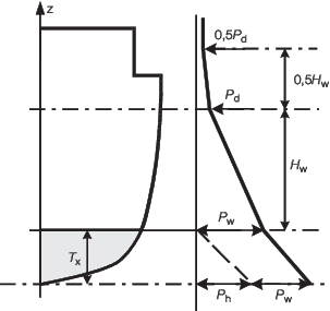
Figure 3.3.1 Combined pressure distributution, Ps
Table 3.3.1 Shell envelope pressure, P
s
| Vertical location
|
Shell envelope pressure,
Ps
|
| i.e. z value
|
kN/m2
|
| for z ≤ T
x + z
k
|
Ph + Pw
|
| i.e. up to the design
waterline
|
|
| At z = Tx + z
k + Hw
|
Pd
|
| At z ≥ Tx +
zk + 1,5Hw
|
0,5Pd
|
| Symbols
|
| Ph
is the hydrostatic pressure, see
Vol 1, Pt 5, Ch 3, 3.3 Hydrostatic pressure on the shell plating, Ph
|
|
Pw is the hydrodynamic wave pressure, see
Vol 1, Pt 5, Ch 3, 3.4 Hydrodynamic wave pressure, Pw
|
| Pd is the
weather deck pressure, see
Vol 1, Pt 5, Ch 3, 3.5 Pressure on exposed and weather decks, Pwd 3.5.2
|
|
Hw is the nominal wave limit height, see
Vol 1, Pt 5, Ch 3, 3.4 Hydrodynamic wave pressure, Pw 3.4.4
|
| Ph and
Pw are to be derived at the appropriate vertical
position, z
|
| Tx, z
and zk are defined in Vol 1, Pt 5, Ch 3, 1.3 Symbols and definitions
|
Note Pressure values at other z values are to be derived
by interpolation.
|
3.4.3 The distribution of hydrodynamic pressure up to the design waterline due to
pitching motion, Pp, is to be taken as:
where
|
Hpm
|
= |
 but not less than but not less than 
|
where
|
L
P
|
= |
L
WL but ≤ 150 m
|
x
wl, L
WL and f
Hs are defined in Vol 1, Pt 5, Ch 3, 1.3 Symbols and definitions.
3.4.4 The nominal wave limit height, Hw, above the design
draught, Tx, is to be taken as:
3.5 Pressure on exposed and weather decks, P
wd
3.5.2 The
minimum design pressure for weather decks, P
d,
above the 0,5H
w limit line and below the 1,0H
w limit line is to be taken as:
-
P
d = 6 + 6f
L
f
Hs kN/m2
where
|
f
L
|
= |
a location factor |
 - but not less than 1,0
L
WL and x
wl are
defined in Vol 1, Pt 5, Ch 3, 1.3 Symbols and definitions
f
Hs is defined in Vol 1, Pt 5, Ch 3, 1.2 Environmental conditions.
3.5.3 If a
bulwark is fitted at the deck edge then consideration will be given
to allowing the height of the top of the bulwark to be used for the
pressure calculation.
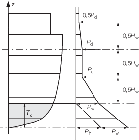
Figure 3.3.2 Weather deck pressure distribution, Pwd
Table 3.3.2 Exposed/weather deck pressure,
P
wd
| Vertical location
|
Exposed/weather deck
pressure, P
wd kN/m2
|
| i.e. z value
|
| for z ≤ T
x + z
k
|
P
h + P
w
|
| i.e. up to the design
waterline
|
|
| At z = Tx + z
k + 0,5H
w
|
P
d
|
| At z = Tx + z
k + 1,0H
w
|
P
d
|
| At z ≥
Tx + z
k + 1,5H
w
|
0,5P
d
|
| Symbols
|
|
P
h is the hydrostatic pressure, see
Vol 1, Pt 5, Ch 3, 3.3 Hydrostatic pressure on the shell plating, Ph
P
w is the hydrodynamic wave pressure, see
Vol 1, Pt 5, Ch 3, 3.4 Hydrodynamic wave pressure, Pw
P
d is the weather deck pressure, see
Vol 1, Pt 5, Ch 3, 3.5 Pressure on exposed and weather decks, Pwd 3.5.2
H
w is the nominal wave limit height, see
Vol 1, Pt 5, Ch 3, 3.4 Hydrodynamic wave pressure, Pw 3.4.4
P
h and P
w are all taken at the appropriate vertical position, z
T
x, z and z
k are defined in Vol 1, Pt 5, Ch 3, 1.3 Symbols and definitions
|
|
NOTE
Pressure values at other z values are to be derived by
interpolation.
|
|