
Section
4 Bulkhead requirements
4.1 Number and disposition of bulkheads
4.1.1 All
ships are to have a collision bulkhead, an after peak bulkhead, generally
enclosing the sterntubes in a watertight compartment, and a watertight
bulkhead at each end of the machinery space. Additional watertight
bulkheads are to be fitted so that the total number of bulkheads is
at least in accordance with Table 3.4.1 Total number of bulkheads.
Table 3.4.1 Total number of bulkheads
| Length, L, in metres
|
Total number of bulkheads
|
|
|
Machinery amidships
|
Machinery aft, see Note
|
|
|
≤ 65
|
4
|
3
|
| > 65
|
≤ 85
|
4
|
4
|
| > 85
|
≤ 90
|
5
|
5
|
| > 90
|
≤ 105
|
5
|
5
|
| > 105
|
≤ 115
|
6
|
5
|
| > 115
|
≤ 125
|
6
|
6
|
| > 125
|
≤ 145
|
7
|
6
|
| > 145
|
≤ 165
|
8
|
7
|
| > 165
|
≤ 190
|
9
|
8
|
| > 190
|
|
To be considered individually
|
Note With after peak bulkhead forming after boundary of
machinery space.
|
4.1.2 The
bulkheads in the holds should be spaced at reasonably uniform intervals.
Where non-uniform spacing is unavoidable and the length of a hold
is unusually great, the transverse strength of the ship is to be maintained
by fitting web frames, increased framing, etc. and details are to
be submitted.
4.1.3 Proposals
to dispense with one or more of these bulkheads will be considered,
subject to suitable structural compensation, if they interfere with
the requirements of a special trade.
4.1.4 Where
applicable, the number and disposition of bulkheads are to be arranged
to suit the requirements for subdivision, floodability and damage
stability, and are to be in accordance with the requirements of the
National Authority in the country in which the ship is registered.
4.2 Collision bulkhead
4.2.1 A collision
bulkhead shall be fitted which shall be watertight up to the bulkhead
deck. This bulkhead shall be located at a distance from the forward
side of the stem, on the waterline on which L
L is
measured, of not less than 0,05L
L or 10 m,
whichever is the less, and, except as may be permitted by the Administration,
not more than 0,08L
L or 0,05L
L +
3 m, whichever is the greater.
4.2.2 Where
any part of the ship below the waterline extends forward of the forward
side of the stem, on the waterline on which L
L is
measured, e.g. a bulbous bow, the distances stipulated in Pt 3, Ch 3, 4.2 Collision bulkhead 4.2.1 are to be measured from a
point either:
-
at the mid-length
of such extension;
-
at a distance
0,015L
L forward of the forward side of the
stem, on the waterline on which L
L is measured;
or
-
at a distance
3 m forward of the forward side of the stem, on the waterline on which L
L is measured, whichever is the least.
4.2.3 No doors,
manholes, access openings, ventilation ducts or any other openings
shall be fitted in the collision bulkhead below the bulkhead deck.
4.3 After peak bulkhead
4.3.1 All ships are to have an after peak bulkhead generally enclosing the
sterntube and rudder trunk in a watertight compartment. In twin screw ships where the
bossing ends forward of the after peak bulkhead, the sterntubes are to be enclosed in
suitable watertight spaces inside or aft of the shaft tunnels. The sterntubes are to be
enclosed in watertight spaces of moderate volume. In passenger ships, the stern gland is
to be situated in a watertight shaft tunnel or other watertight space separate from the
sterntube compartment and of such volume that, if flooded by leakage through the stern
gland, the bulkhead deck will not be submerged.
4.4 Height of bulkheads
4.4.1 The
collision bulkhead is normally to extend to the uppermost continuous
deck or, in the case of ships with combined bridge and forecastle
or a long superstructure which includes a forecastle, to the superstructure
deck. However, if a ship is fitted with more than one complete superstructure
deck, the collision bulkhead may be terminated at the deck next above
the freeboard deck. Where the collision bulkhead extends above the
freeboard deck, the extension need only be to weathertight standards.
4.4.2 The
after peak bulkhead may terminate at the first deck above the load
waterline, provided that this deck is made watertight to the stern
or to a watertight transom floor. In passenger ships, the after peak
bulkhead is to extend watertight to the bulkhead deck. However, it
may be stepped below the bulkhead deck provided the degree of safety
of the ship as regards watertight subdivision is not thereby diminished.
4.4.3 The
remaining watertight bulkheads are to extend to the freeboard deck.
In passenger ships of restricted draught and all ships of unusual
design, the height of the bulkheads will be specially considered.
4.5 Watertight recesses, flats and loading ramps
4.5.1 Watertight
recesses in bulkheads are generally to be so framed and stiffened
as to provide strength and stiffness equivalent to the requirements
for watertight bulkheads.
4.5.2 In collision
bulkheads, any recesses or steps in the bulkhead are to fall within
the limits of bulkhead positions given in Pt 3, Ch 3, 4.2 Collision bulkhead 4.2.1. Where the bulkhead is extended
above the freeboard deck or bulkhead deck, the extension need only
be to weathertight standards. If a step occurs at that deck, the deck
need also only be to weathertight standards in way of the step, unless
the step forms the crown of a tank, see
Pt 4, Ch 1, 4 Deck structure.
4.5.3 Where
bow doors are fitted and a sloping loading ramp forms part of the
extension of the collision bulkhead above the bulkhead deck the ramp
shall be weathertight over its complete length. In cargo ships the
part of the ramp which is more than 2,3 m above the bulkhead deck
may extend forward of the limit specified in Pt 3, Ch 3, 4.2 Collision bulkhead 4.2.1 or Pt 3, Ch 3, 4.2 Collision bulkhead 4.2.2. Ramps not meeting the above
requirements shall be disregarded as an extension of the collision
bulkhead.
4.5.4 The
number of openings in the extension of the collision bulkhead above
the freeboard deck shall be restricted to the minimum compatible with
the design and normal operation of the ship. All such openings shall
be capable of being closed weathertight.
4.6 Longitudinal subdivision
4.6.1 When
timber load lines are to be assigned, double bottom tanks within the
midship half-length are to have adequate longitudinal subdivision.
4.7 Separation and protection of tanks
4.7.1 Where the cross contamination of liquids stored in adjacent tanks is
hazardous to machinery, these tanks are to be separated by cofferdams. Hazardous
pairings of liquid consumables include but are not limited to the following:
- Fuel oil and lubricating oil;
- Fuel oil and technical water (e.g. feedwater);
- Lubricating oil and technical water;
- Fuel oil and urea.
4.7.2 Tanks carrying liquids for the purposes of fire fighting (e.g. foam
concentrate) are to be separated by cofferdams from adjacent tanks containing liquid
fuels.
4.7.3 Tanks carrying fresh water for human consumption (potable water) are to
be separated by cofferdams from adjacent tanks containing liquid substances harmful
to human health. Fresh water for other purposes and water ballast are not considered
harmful.
4.7.4 Where a cofferdam as specified in Pt 3, Ch 3, 4.7 Separation and protection of tanks 4.7.1 is
impracticable, special consideration may be given, subject to the arrangements
complying with the following:
- The thickness of common boundary plates is increased by 1 mm;
- Common boundaries have full penetration welds.
4.7.5 Where a corner to corner situation occurs, tanks are not considered to be
adjacent.
4.7.6 Where fitted, cofferdams are to be suitably ventilated, provided with a
suitable drainage arrangement, see
Pt 5, Ch 13, 3.5 Tanks and cofferdams, and be of
sufficient size to allow proper inspection, maintenance and safe evacuation.
4.7.8 For vessels which do not comply with the accidental fuel oil outflow
performance standard given in MARPOL Annex 1, Regulation
12A-11, fuel oil tanks are to be bounded by
double bottom and double side tanks or void spaces such that the distance between
the fuel oil tank boundary and the shell plating is not less than that given in
Table 3.4.2 Fuel oil tank boundary
requirements and Figure 3.4.1 Fuel oil tank boundary
lines. For double hull oil tankers
where the requirements of Pt 4, Ch 9, 1.2 Application and ship arrangement 1.2.17 conflict with this requirement Pt 4, Ch 9, 1.2 Application and ship arrangement 1.2.17 is to take precedent. Alternatively
the accidental oil outflow performance standard specified in MARPOL Annex 1 Regulation 12A may be complied with.
Table 3.4.2 Fuel oil tank boundary
requirements
Fuel oil tank
capacity (C),
|
Minimum double
side
width (d
s)
|
Minimum double
bottom depth (d
b)
|
m3
|
metres
|
metres
|
|
C ≥ 5000
|

|

|
|
|
or
|
or
|
|
|
d
s = 2,0
|
d
b = 2,0
|
|
|
whichever is the
lesser,
but not less than 1,0
|
whichever is the
lesser,
but not less than 0,76
|
| 600 ≤ C < 5000
|

|

|
|
|
or
|
or
|
|
|
d
s = 1,0
|
d
b = 2,0
|
|
|
whichever is the
greater,
see Note
|
whichever is the
lesser,
but not less than 0,76
|
|
C < 600
|
d
s = 0
|
d
b = 0
|
| Symbols
|
|
C
|
= |
the ship’s total volume of fuel oil,
including that of small fuel oil tanks, in
m3, at 98 per cent tank filling |
|
db
|
= |
the distance, in metres, between the bottom
of the fuel oil tank and the moulded line of the bottom
shell plating. In the turn of bilge area and at
locations without a clearly defined turn of bilge, the
fuel oil tank boundary line shall run parallel to the
line of the midship flat bottom as shown in Figure 3.4.2 Definition of
db
|
|
Note
1. However, for individual
tanks with an fuel oil capacity of less than 500
m3, the minimum distance is 0,76 m.
Note
2. Fuel oil tanks with a
maximum individual capacity not greater than 30
m3 need not comply with the requirements of
this Table, provided the aggregate capacity of such excluded
tanks is not greater than 600 m3.
Note
3. Suction wells in fuel oil
tanks may protrude into the double bottom below the boundary
line defined by the distance d
b, provided that such wells are as small as
practicable and the distance between the well bottom and the
bottom shell plating is not less than 0,5d
b.
|
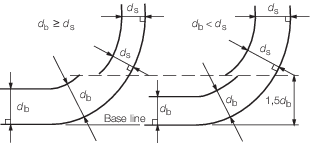
Figure 3.4.1 Fuel oil tank boundary
lines

Figure 3.4.2 Definition of
db
4.7.9 No individual fuel oil tank is to have a capacity greater than 2,500
m3.
4.8 Watertight tunnels and passageways
4.8.1 Where
a machinery space is situated with a compartment or compartments between
it and the after peak bulkhead, the shafting is to be enclosed in
a watertight tunnel large enough to permit proper examination and
repair of shafting. A sliding watertight door, capable of being operated
locally from both sides, is to be provided at the forward end of the
tunnel. Consideration may, however, be given to the omission of the
watertight door, subject to satisfactory compliance with any relevant
statutory requirements. Where two or more shafts are fitted, the tunnels
shall be connected by an interconnecting passage. There shall be only
one door between the machinery space and the tunnel spaces where two
shafts are fitted and only two doors where there are more than two
shafts.
4.8.2 Pipe
tunnels are to have dimensions adequate for reasonable access.
4.8.3 Where
fore and aft underdeck passageways are arranged at the ship's side,
the after access thereto is to be by a watertight trunk led to the
upper deck. Alternative arrangements to prevent the engine room being
flooded, in the event of a collision or if the passageway doors are
left open, will be considered.
4.9 Means of escape
4.10 Oil tankers
4.10.1 For
subdivision requirements within the cargo tank region for oil tankers, see
Pt 4, Ch 9, 1 General.
|