
Section
3 Structural idealisation
3.1 General
3.1.1 For
derivation of scantlings of stiffeners, beams, girders, etc. the formulae
in the Rules are normally based on elastic or plastic theory using
simple beam models supported at one or more points and with varying
degrees of fixity at the ends, associated with an appropriate concentrated
or distributed load.
3.1.2 Apart
from local requirement for web thickness or flange thicknesses, the
stiffener, beam or girder strength is defined by a section modulus
and moment of inertia requirement.
3.2 Geometric properties of section
3.2.1 The
symbols used in this sub-Section are defined as follows:
|
b
|
= |
the
actual width, in metres, of the load-bearing plating, i.e. one-half
of the sum of spacings between parallel adjacent members or equivalent
supports |
|
t
p
|
= |
the thickness, in mm, of the attached plating. Where this varies,
the mean thickness over the appropriate span is to be used. |
Table 3.3.1 Load bearing plating
factor

|
f
|

|
f
|
| 0,5
|
0,19
|
3,5
|
0,69
|
| 1,0
|
0,30
|
4,0
|
0,76
|
| 1,5
|
0,39
|
4,5
|
0,82
|
| 2,0
|
0,48
|
5,0
|
0,88
|
| 2,5
|
0,55
|
5,5
|
0,94
|
| 3,0
|
0,62
|
6 and
above
|
1,00
|
Note Intermediate values to be obtained by linear
interpolation.
|
3.2.2 The
effective geometric properties of rolled or built sections may be
calculated directly from the dimensions of the section and associated
effective area of attached plating. Where the web of the section is
not normal to the attached plating, and the angle exceeds 20°,
the properties of the section are to be determined about an axis parallel
to the attached plating.
3.2.3 The
geometric properties of rolled or built stiffener sections and of
swedges are to be calculated in association with effective area of
attached load bearing plating of thickness t
p mm
and of width 600 mm or 40t
p mm, whichever
is the greater. In no case, however, is the width of plating to be
taken as greater than either the spacing of the stiffeners or the
width of the flat plating between swedges, whichever is appropriate.
The thickness, t
p, is the actual thickness
of the attached plating. Where this varies, the mean thickness over
the appropriate span is to be used.
3.2.4 The
effective section modulus of a corrugation over a spacing p is
to be calculated from the dimensions and, for symmetrical corrugations,
may be taken as:
where d
w
, b, t
p
, c and t
w are measured,
in mm, and are as shown in Figure 3.3.1 Corrugation dimensions.
The value of b is to be taken not greater than:
The value of θ is to be not less than 40°.
The moment of inertia is to be calculated from:
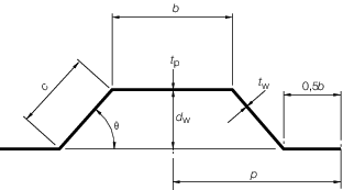
Figure 3.3.1 Corrugation dimensions
3.2.5 The
section modulus of a double plate bulkhead over a spacing b may
be calculated as:
where d
w
, b, t
p and t
w are measured, in mm, and are
as shown in Figure 3.3.2 Double plate bulkhead dimensions .
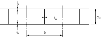
Figure 3.3.2 Double plate bulkhead dimensions
3.2.6 The
effective section modulus of a built section may be taken as:
where
|
a
|
= |
the
area of the face plate of the member, in cm2
|
|
d
w
|
= |
the depth, in mm, of the web between the inside of the face
plate and the attached plating. Where the member is at right angles
to a line of corrugations, the minimum depth is to be taken |
|
t
w
|
= |
the thickness of the web of the section, in mm |
|
A
|
= |
the
area, in cm2, of the attached plating, see
Pt 3, Ch 3, 3.2 Geometric properties of section 3.2.7. If the calculated value of A is less than the face area a, then A is
to be taken as equal to a.
|
3.2.7 The
geometric properties of primary support members (i.e. girders, transverses,
webs, stringers, etc.) are to be calculated in association with an
effective area of attached load bearing plating, A, determined
as follows:
-
For a member attached
to plane plating:
-
For a member attached
to corrugated plating and parallel to the corrugations:
See
Figure 3.3.1 Corrugation dimensions
-
For a member attached
to corrugated plating and at right angles to the corrugations:
|
A |
= |
is
to be taken as equivalent to the area of the face plate of the member. |
3.3 Determination of span point
3.3.1 The
effective length,  e, of a stiffening member is generally less
than the overall length,
e, of a stiffening member is generally less
than the overall length,  , by an amount which depends on the design of the end connections.
The span points, between which the value of , by an amount which depends on the design of the end connections.
The span points, between which the value of  e is measured, are to be determined as follows:
-
For rolled or
built secondary stiffening members:
The span point is to be taken at the point where the depth of
the end bracket, measured from the face of the secondary stiffening
member is equal to the depth of the member. Where there is no end
bracket, the span point is to be measured between primary member webs.
For double skin construction, the span may be reduced by the depth
of primary member web stiffener, see
Figure 3.3.3 Span points.
-
For primary support
members:
The span point is to be taken at a point distant from the end
of the member,
See also
Figure 3.3.3 Span points.
3.3.2 Where
the end connections of longitudinals are designed with brackets to
achieve compliance with the ShipRight FDA procedure,
no reduction in span is permitted for such brackets unless the fatigue
life is subsequently re-assessed and shown to be adequate for the
resulting reduced scantlings.
3.3.3 Where
the stiffener member is inclined to a vertical or horizontal axis
and the inclination exceeds 10°, the span is to be measured along
the member.
3.3.4 It is
assumed that the ends of stiffening members are substantially fixed
against rotation and displacement. If the arrangement of supporting
structure is such that this condition is not achieved, consideration
will be given to the effective span to be used for the stiffener.
3.4 Calculation of hull section modulus
3.4.1 All continuous longitudinal structural material is to be included in the
calculation of the inertia of the hull midship section, and the lever z is,
except where otherwise specified for particular ship types, to be measured vertically
from the neutral axis to the top of keel and to the moulded strength deck line at the
side. The strength deck is to be taken as follows:
-
Where there is a complete upper deck and no effective superstructure,
the strength deck is the upper deck.
-
Where the upper deck is stepped, as in the case of a raised
quarterdeck or a long forecastle, or there is an effective superstructure on the
upper deck, the strength deck is stepped
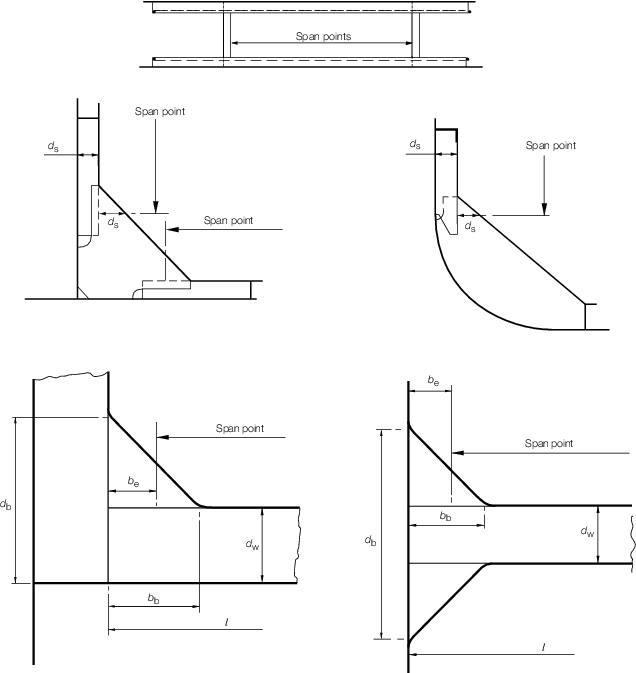
Figure 3.3.3 Span points
3.4.2 A transition zone, see
Figure 3.3.4 Midship strength deck
stepping and Figure 3.3.5 Local strength deck
stepping, is to be assumed at the ends of effective superstructures and at the
end of stepped decks, where the longitudinal material cannot be included in the
calculation of the hull section modulus. The length of the zone is to be taken as four
times the deck height. Local insert plates are to be fitted in the side shell as
appropriate with a thickness at least 25 per cent greater than the adjacent plating.
They are to extend a minimum of one primary frame spacing forward and aft, but are to be
not less than 1500 mm each way from the end of the transition zone. For vessels with
complex arrangements or geometries, shadow plan areas are to be submitted.
3.4.3 A superstructure deck or stepped deck can only be considered as the strength deck and
included in the calculation of hull midship section modulus if it extends at least the
complete 0,4L amidships and transversely to the side shell with transition zones
being located aft and forward (as appropriate) outside of this length.
3.4.4 A superstructure deck or stepped deck can only be considered effective and used in local
section modulus calculations if it extends at least 0,15L and transversely to the
side shell with the transition zones being located aft and forward outside of this
length.
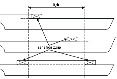
Figure 3.3.4 Midship strength deck
stepping
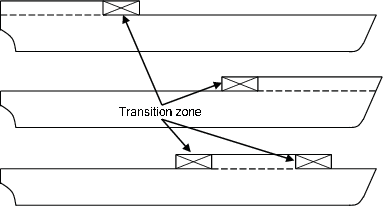
Figure 3.3.5 Local strength deck
stepping
3.4.5 Openings having a length in the fore and aft directions exceeding 2,5 m or
0,1B m or a breadth exceeding 1,2 m or 0,04B m, whichever is the
lesser, are always to be deducted from the sectional areas used in the section modulus
calculation.
3.4.6 Smaller openings (including manholes, lightening holes, single scallops in
way of seams, etc.) need not be deducted provided they are isolated and the sum of their
breadths or shadow area breadths (see
Pt 3, Ch 3, 3.4 Calculation of hull section modulus 3.4.9), in one transverse section does not reduce the
section modulus at deck or bottom by more than 3 per cent.
3.4.7 Where B
1 equals the breadth of the ship at the section considered and Σb
1 equals the sum of breadths of deductible openings, the expression 0,06
(B
1 – Σb) may be used for deck openings in lieu of the 3 per cent
limitation of reduction of section modulus in Pt 3, Ch 3, 3.4 Calculation of hull section modulus 3.4.6.
3.4.8 Where a large number of openings are proposed in any transverse space,
special consideration will be required.
3.4.9 When calculating deduction-free openings, the openings are assumed to have
longitudinal extensions as shown by the shaded areas in Figure 3.3.6 Deduction free openings shadow
areas. The shadow area is obtained by drawing two
tangent lines to an opening angle of 30° . The section to be considered should be
perpendicular to the centreline of the ship and should result in the maximum deduction
in each transverse space.
3.4.10 Isolated openings in longitudinals or longitudinal girders need not be
deducted if their depth does not exceed 25 per cent of the web depth with a maximum
depth for scallops of 75 mm.
3.4.11 Openings are considered isolated if they are spaced not less than 1 m
apart.
3.4.12 For compensation that may be required for openings, see individual
ship Chapters.
3.4.13 Where trunk decks or continuous hatch coamings are effectively supported by
longitudinal bulkheads or deep girders, they are to be included in the longitudinal
sectional area when calculating the hull section modulus. The lever z
t is to be taken as:
|
z
t
|
= |
zc(0,9 + 0,2 ) m but not less than z ) m but not less than z
|
|
y
|
= |
horizontal distance from top of continuous strength member to the
centreline of the ship, in metres |
|
z
|
= |
vertical distance from the neutral axis to the moulded deck line at
side, in metres |
|
z
c
|
= |
vertical distance from the neutral axis to the top of the continuous
strength member, in metres |
z
c and y are to be measured to the point giving the largest value of
z
t.
3.4.14 Where continuous hatch coamings are effectively supported (except inboard
coamings of multi-hatch arrangements, see
Pt 3, Ch 3, 3.4 Calculation of hull section modulus 3.4.16), 100 per cent of their sectional area may be
included in the calculation of the hull section modulus.
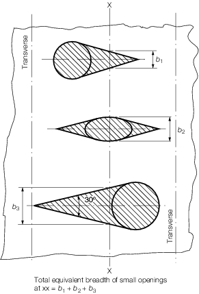
Figure 3.3.6 Deduction free openings shadow
areas
3.4.15 Where a continuous longitudinal underdeck girder, or girders, are arranged
to support the inboard hatch coamings, 50 per cent of their sectional area may be
included. If the girder is fitted in conjunction with a longitudinal centreline
bulkhead, 100 per cent of the sectional area may be included. In cases where the girders
are enclosed box sections, or where the girders are effectively tied to the bottom
structure, the area to be included will be specially considered.
3.4.16 The percentage of the sectional area to be included for inboard continuous
hatch side coamings should be the same percentage as that of the longitudinal girder
under.
3.4.17 Where continuous deck longitudinals or deck girders are arranged above the
strength deck, the sectional area may be included in the calculation of the hull section
modulus. The lever is to be taken to a position corresponding to the depth of the
longitudinal member above the moulded deckline at side amidships.
|