
Section
2 Fracture control
2.1 Grades of steel
2.1.1 The
resistance to fracture is controlled, in part, by the notch toughness
of the steel used in the structure. Steels with different levels of
notch toughness are specified in the Rules for the Manufacture, Testing and Certification of Materials, July 2022. The grade of steel to be used is, in general, related to
the thickness of the material and the stress pattern associated with
its location.
2.1.2 In order
to distinguish between the material grade requirements for different
hull members at varying locations along the ship, material classes
are assigned as shown in Table 2.2.1 Material classes and
grades.
For each class, depending on thickness, the material grade requirements
are not to be lower than those given in Table 2.2.2 Steel grades.
2.1.3 Where
tee or cruciform connections employ full penetration welds, and the
plate material is subject to significant strains in a direction perpendicular
to the rolled surfaces, it is recommended that consideration be given
to the use of special plate material with specified through thickness
properties, as detailed in Ch 3, 8 Plates with specified through thickness properties of
the Rules for Materials.
2.1.4 Design
for normal worldwide service assumes the navigation to areas of minus
10°C, where the design air temperature is to be taken as the lowest
mean daily average air temperature in the area of operation:
where
|
Mean |
= |
statistical
mean over a minimum of 20 years |
|
Average |
= |
average
during one day and one night |
|
Lowest |
= |
lowest during
the year |
|
MDHT |
= |
Mean Daily
High Temperature |
|
MDAT |
= |
Mean Daily
Average Temperature |
|
MDLT |
= |
Mean Daily
Low Temperature |
Figure 2.2.1 Design air temperature shows the
definition graphically.
The material grade of exposed structure of ships intended to operate in
external air temperatures below minus 10°C is to be in accordance with Pt 3, Ch 2, 2.3 Structures exposed to low temperatures.
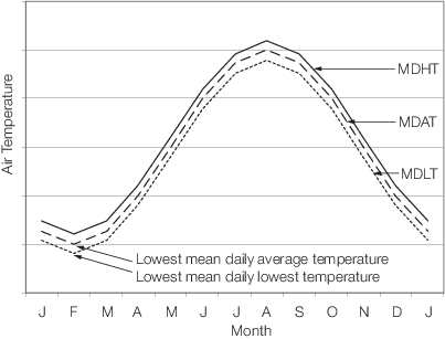
Figure 2.2.1 Design air temperature
2.2 Refrigerated spaces
2.2.2 Unless
a temperature gradient calculation is carried out to assess the design
temperature in the items defined in Pt 3, Ch 2, 2.2 Refrigerated spaces 2.2.1, the temperature to which the steel deck may be subjected
is to be assessed as shown in Table 2.2.4 Assessment of deck
temperature.
Table 2.2.1 Material classes and
grades
| Structural member category
|
Material class/Minimum grade
|
| SECONDARY
|
| A1.
|
Longitudinal bulkhead strakes, other
than belonging to the Primary category
|
|
| A2.
|
Deck plating exposed to
weather, other than that belonging to the Primary or Special
category
|
Class I within 0,4L amidships
|
| A3.
|
Side plating
|
Grade A/AH outside 0,4L amidships
|
| PRIMARY
|
| B1.
|
Bottom plating,
including keel plate
|
|
| B2.
|
Strength deck plating,
excluding that belonging to the Special category
|
|
| B3.
|
Continuous longitudinal
plating of strength members above strength deck, excluding hatch
coamings
|
Class II within 0,4L amidships
|
| B4.
|
Uppermost strake in
longitudinal bulkhead
|
Grade A/AH outside 0,4L amidships
|
| B5.
|
Vertical strake (hatch
side girder) and uppermost sloped strake in top wing tank
|
|
| SPECIAL
|
| C1.
|
Sheerstrake
(or rounded gunwale) and stringer plate at strength deck, see Note 1
|
Class III within 0,4L amidships
|
| C2.
|
Deck strake at
longitudinal bulkhead excluding deck plating in way of inner skin bulkhead
of double hull ships, see Note 1
|
Class II outside 0,4L amidships
|
| Class I outside 0,6L amidships
|
| C3.
|
Strength deck plating at outboard
corners of cargo hatch openings (and plating intersections of the
longitudinal underdeck girders and the cross-deck strips) in container
carriers and other ships with similar hatch opening configurations
|
Class III within 0,4L amidships
|
|
|
|
Class II outside 0,4L amidships
|
|
|
|
Class I outside 0,6L amidships
|
|
|
|
Minimum Class III within cargo region
|
| C4.
|
Strength deck plating at corners of
cargo hatch openings in bulk carriers (see
Pt 3, Ch 2, 1.1 General 1.1.3), ore carriers, combination carriers and
other ships with similar hatch opening configurations
|
Class III within 0,6L amidships
|
| C5.
|
Trunk deck
and inner deck plating at corners of openings for liquid and gas domes in
membrane type liquefied gas carriers
|
Class II within rest of cargo region
|
| C6.
|
Bilge strake in ships with double
bottom over the full breadth and length less than 150 m
|
Class II within 0,6L amidships
|
|
|
|
Class I outside 0,6L amidships
|
| C7.
|
Bilge strake in other ships ,
see Note 1
|
Class III within 0,4L amidships
|
|
|
|
Class II outside 0,4L amidships
|
|
|
|
Class I outside 0,6L amidships
|
| C8
|
Longitudinal hatch coamings of length
greater than 0,15L including coaming top plate and flange
|
Class III within 0,4L
amidships
|
|
|
|
Class II outside 0,4L amidships
|
| C9.
|
End
brackets and deck house transition of longitudinal cargo hatch
coamings
|
Class I outside 0,6L amidships Not to be less than Grade
D/DH
|
| ADDITIONAL MINIMUM REQUIREMENTS FOR SINGLE STRENGTH
DECK SHIPS OF LENGTH GREATER THAN 150 m
|
| D1.
|
Longitudinal plating of strength deck where contributing to the
longitudinal strength
|
Grade B/AH within 0,4L amidships
|
| D2.
|
Continuous
longitudinal plating of strength members above strength deck
|
|
| D3
|
Continuous
longitudinal trunk deck plating of membrane type liquefied gas
carriers
|
Class II within 0,4L amidships
|
| D4
|
Single side
strakes for ships without inner continuous longitudinal bulkhead(s) between
bottom and strength deck
|
Grade B/AH within cargo region
|
| ADDITIONAL MINIMUM REQUIREMENTS FOR SHIPS OF LENGTH
GREATER THAN 250 m
|
| E1.
|
Sheerstrake
(or rounded gunwale) and stringer plate at strength deck, see Note 2
|
Grade E/EH within 0,4L amidships
|
| E2.
|
Bilge
strake, see Note 2
|
Grade D/DH within 0,4L amidships
|
| ADDITIONAL MINIMUM REQUIREMENTS FOR SINGLE SKIN BULK
CARRIERS SUBJECTED TO SOLAS REGULATION XII/6.4
|
| F1.
|
Lower
bracket of ordinary side frame, see Notes 6 and 7
|
Grade D/DH
|
| F2.
|
Side shell
strakes included totally or partially between the two points located to
0,125l above and below the intersection of side shell and bilge hopper
sloping plate or inner bottom plate, see Note 7
|
Grade D/DH
|
Note
1. Single strakes required to be of Class
III and within 0,4L amidships are to have breadths not less
than 800 + 5L mm, but need not be greater than 1800 mm, unless
limited by the geometry of the ship’s design.
Note
2. Single strakes required to be of Grade
D/DH or Grade E/EH and within 0,4L amidships are to have
breadths not less than 800 + 5L mm, but need not be greater
than 1800 mm, unless limited by the geometry of the ship’s design.
Note
3. For strength members not mentioned,
Grade A/AH may be generally used.
Note
4. Steel grade is to correspond to the
as-fitted thickness.
Note
5. Plating materials for sternframes
supporting the rudder and propeller boss, rudders, rudder horns and
shaft brackets are, in general, not to be of lower grades than
corresponding to Class II. For rudder and rudder body plates subjected
to stress concentrations (e.g. in way of lower support of semi-spade
rudders or at upper part of spade rudders) Class III is to be
applied.
Note
6. The term ‘lower bracket’ means webs of
lower brackets and webs of the lower part of side frames up to the
point of 0,125l above the intersection of side shell and bilge hopper
sloping plate or inner bottom plate.
Note
7. The span of the side frame, l, is
defined as the distance between the supporting structures.
Note
8. Corner inserts in way of complex
openings such as for lifts and side doors which may impinge on the
deck plating or stringer plate are to be of Grade D/DH for t ≤
20 mm and Grade E/EH for t > 20 mm.
Note
9. The material class used for
reinforcement and the quality of material (i.e. whether mild or higher
tensile steel) used for welded attachments, such as waterway bars and
bilge keels, is to be similar to that of the hull envelope plating in
way. Where attachments are made to rounded gunwale plates, special
consideration will be given to the required grade of steel, taking
account of the intended structural arrangements and attachment
details.
Note
10. The material class for deck plating,
sheer strake and upper strake of longitudinal bulkhead within 0,4L
amidships is also to be applied at structural breaks of the
superstructure, irrespective of position.
Note
11. Engine seat top plates outside
0,6L amidships may be Grade A/AH. Steel grade requirement
for top plates within 0,6L amidships will be specially
considered.
|
Table 2.2.2 Steel grades
| Thickness, t, in mm
|
Material class
|
|
|
I
|
II
|
III
|
|
|
Mild steel
|
H.T. steel
|
Mild
steel
|
H.T.
steel
|
Mild
steel
|
H.T.
steel
|
|
t ≤ 15
|
A
|
AH
|
A
|
AH
|
A
|
AH
|
| 15 < t ≤ 20
|
A
|
AH
|
A
|
AH
|
B
|
AH
|
| 20 < t ≤
25
|
A
|
AH
|
B
|
AH
|
D
|
DH
|
| 25 < t ≤
30
|
A
|
AH
|
D
|
DH
|
D
|
DH
|
| 30 < t ≤
35
|
B
|
AH
|
D
|
DH
|
E
|
EH
|
| 35 < t ≤
40
|
B
|
AH
|
D
|
DH
|
E
|
EH
|
| t >
40
|
D
|
DH
|
E
|
EH
|
E
|
EH
|
|
Note
See Notes under
Table 2.2.1 Material classes and
grades
|
Table 2.2.3 Grades of steel for refrigerated
spaces with a minimum design temperatures below 0°C
Minimum
design
temperature, in °C
|
Thickness, in mm
|
Grades of
steel
|
| <0 to –10
|
|
t ≤ 12,5
|
B/AH
|
|
|
12,5
|
t ≤ 25,5
|
D/DH
|
|
|
|
t > 25,5
|
E/EH
|
| <–10 to –25
|
|
t ≤ 12,5
|
D/DH
|
|
|
|
t > 12,5
|
E/EH
|
| <– 25
to –40
|
|
t ≤
12,5
|
E/EH
|
|
|
|
t
> 12,5
|
FH/LT–FH,
|
Table 2.2.4 Assessment of deck
temperature
| Arrangement
|
Deck
temperature
|
| (1) Deck not
covered with insulation in the refrigerated space
|
Temperature of the refrigerated
space
|
| (2) Deck
covered with insulation in the refrigerated space and not insulated on the
other side
|
Temperature of the space on the
uninsulated side
|
| (3) Deck
covered with insulation on both sides
|
|
| (a)
Temperature difference not greater than 11°C
|
Mean of the temperatures of the
spaces above and below the deck
|
| (b)
Temperature difference greater than 11°C but not greater than 33°C
|
Mean of the temperatures of the
spaces above and below the deck less 3°C
|
| (c)
Temperature difference greater than 33°C
|
Deck temperature will be
specially assessed
|
Note Where one of the internal spaces concerned is not
refrigerated, the temperature of the space is to be taken as 5°C.
|
2.3 Structures exposed to low temperatures
2.3.3 For ships where the optional Winterisation H notation is applied, see
Rules for the Winterisation of Ships, July 2022, note that the external design air
temperature defined in the Winterisation Rules is taken as 13°C lower than the
design air temperature, i.e. if the design air temperature is −11°C, then the
external design air temperature for the application of the Winterisation Rules is
−24°C.
2.4 Carriage of cold cargoes
2.4.1 For ships other than liquefied gas carriers, which are intended to be
loaded with liquid cargo having a temperature below −10°C, e.g. loading from cold
onshore storage tanks during winter conditions, the grade of steel for the cargo
tank boundary plating is to comply with the requirements of Table 2.2.6 Materials for Class I for low air temperatures where the design air temperature is to be taken as
the design minimum cargo temperature in °C. The design minimum cargo temperature is
to be specified in the Loading Manual, see
Pt 3, Ch 4, 8.2 Loading Manual 8.2.4.
Table 2.2.5 Material classes and grades for structures exposed to low air temperatures
| Structural member category
|
Material class
|
| Within 0,4 L
amidships
|
Outside 0,4
L amidships
|
| SECONDARY
|
I
|
I
|
- Deck plating exposed to weather, in
general
- Side plating above CWL, see Note
5
- Transverse bulkheads above CWL,
see Notes 5 and 6
|
|
|
| PRIMARY
|
II
|
I
|
- Strength deck plating
- Continuous longitudinal members above
strength deck, excluding longitudinal hatch coamings
- Longitudinal bulkhead above CWL,
see Notes 5 and 6
- Top wing tank bulkhead above CWL,
see Notes 5 and 6
|
|
|
| SPECIAL
|
III
|
II
|
- Sheerstrake at strength deck, see
Note 1
- Stringer plate in strength deck,
see Note 1
- Deck strake at longitudinal bulkhead,
see Note 2
- Continuous longitudinal hatch coamings,
see Note 3
|
|
|
|
Note 1. Not to be less than Grade E/EH within 0,4L amidships in
ships with length exceeding 250 m.
Note 2. In ships with breadth exceeding 70 m at least three deck
strakes are to be Class III.
Note 3. Not to be less than Grade D/DH.
Note 4. Within 0,4L amidships, single strakes which are required to
be of Class III or of Grade E/EH or FH are to have breadths not
less than 800 + 5L, but need not be taken greater than 1800
mm.
Note 5. The Cold Waterline (CWL) is to be taken as 0,3 m below the
minimum design Ballast Waterline (BWL).
Note 6. Applicable to plating attached to hull envelope plating
exposed to cold air. At least one strake is to be considered in
the same way as exposed plating and the strake width is to be at
least 600 mm. If thermal stress calculations are performed, then
the extent of plate requiring consideration is to be adjusted
accordingly.
|
Table 2.2.6 Materials for Class I for low air temperatures
| Thickness, mm
|
Design air temperature
|
| −11°C to −15°C
|
−16°C to −25°C
|
−26°C to −35°C
|
−36°C to −45°C
|
−46°C to −55°C
|
| MS
|
HT
|
MS
|
HT
|
MS
|
HT
|
MS
|
HT
|
MS
|
HT
|
| t ≤
10
|
A
|
AH
|
A
|
AH
|
B
|
AH
|
D
|
DH
|
D
|
DH
|
| 10 <
t ≤ 15
|
A
|
AH
|
B
|
AH
|
D
|
DH
|
D
|
DH
|
D
|
DH
|
| 15 <
t ≤ 20
|
A
|
AH
|
B
|
AH
|
D
|
DH
|
D
|
DH
|
E
|
EH
|
| 20 <
t ≤ 25
|
B
|
AH
|
D
|
DH
|
D
|
DH
|
D
|
DH
|
E
|
EH
|
| 25 <
t ≤ 30
|
B
|
AH
|
D
|
DH
|
D
|
DH
|
E
|
EH
|
E
|
EH
|
| 30 <
t ≤ 35
|
D
|
DH
|
D
|
DH
|
D
|
DH
|
E
|
EH
|
E
|
EH
|
| 35 <
t ≤ 45
|
D
|
DH
|
D
|
DH
|
E
|
EH
|
E
|
EH
|
n/a
|
FH
|
| 45 <
t ≤ 50
|
D
|
DH
|
E
|
EH
|
E
|
EH
|
n/a
|
FH
|
n/a
|
FH
|
|
Note MS and HT are defined as Mild Steel and High Tensile Steel
respectively.
|
Table 2.2.7 Materials for Class II for low air temperatures
| Thickness, mm
|
Design air temperature
|
| −11°C to −15°C
|
−16°C to −25°C
|
−26°C to −35°C
|
−36°C to −45°C
|
−46°C to −55°C
|
| MS
|
HT
|
MS
|
HT
|
MS
|
HT
|
MS
|
HT
|
MS
|
HT
|
| t ≤ 10
|
A
|
AH
|
B
|
AH
|
D
|
DH
|
D
|
DH
|
E
|
EH
|
| 10 < t ≤ 20
|
B
|
AH
|
D
|
DH
|
D
|
DH
|
E
|
EH
|
E
|
EH
|
| 20 < t ≤ 30
|
D
|
DH
|
D
|
DH
|
E
|
EH
|
E
|
EH
|
n/a
|
FH
|
| 30 < t ≤ 40
|
D
|
DH
|
E
|
EH
|
E
|
EH
|
n/a
|
FH
|
n/a
|
FH
|
| 40 < t ≤ 45
|
E
|
EH
|
E
|
EH
|
n/a
|
FH
|
n/a
|
FH
|
n/a
|
n/a
|
| 45 < t ≤ 50
|
E
|
EH
|
E
|
EH
|
n/a
|
FH
|
n/a
|
FH
|
n/a
|
n/a
|
| Note. MS and
HT are defined as Mild Steel and High Tensile Steel
respectively.
|
Table 2.2.8 Materials for Class III for low air temperatures
| Thickness, mm
|
Design air
temperature
|
| −11°C to −15°C
|
−16°C to −25°C
|
−26°C to −35°C
|
−36°C to −45°C
|
−46°C to −55°C
|
| MS
|
HT
|
MS
|
HT
|
MS
|
HT
|
MS
|
HT
|
MS
|
HT
|
| t ≤
10
|
B
|
AH
|
D
|
DH
|
D
|
DH
|
E
|
EH
|
E
|
EH
|
| 10 <
t ≤ 20
|
D
|
DH
|
D
|
DH
|
E
|
EH
|
E
|
EH
|
n/a
|
FH
|
| 20 <
t ≤ 25
|
D
|
DH
|
E
|
EH
|
E
|
EH
|
E
|
FH
|
n/a
|
FH
|
| 25 <
t ≤ 30
|
D
|
DH
|
E
|
EH
|
E
|
EH
|
n/a
|
FH
|
n/a
|
FH
|
| 30 <
t ≤ 35
|
E
|
EH
|
E
|
EH
|
n/a
|
FH
|
n/a
|
FH
|
n/a
|
n/a
|
| 35 <
t ≤ 40
|
E
|
EH
|
E
|
EH
|
n/a
|
FH
|
n/a
|
FH
|
n/a
|
n/a
|
| 40 <
t ≤ 50
|
E
|
EH
|
n/a
|
FH
|
n/a
|
FH
|
n/a
|
n/a
|
n/a
|
n/a
|
|
Note MS and HT are defined as Mild Steel and High Tensile Steel
respectively.
|
|