
Section
3 Panel scantling requirements – decks loaded by wheeled
vehicles
3.1 Application
3.2 Decks loaded by wheeled vehicles
3.2.1 The scantlings of vehicle deck panels are to satisfy the most severe arrangement of
print wheel loads.
3.2.2 The deck
plate thickness is to be not less than:
where
|
t
a1, t
a2
|
= |
1,5 mm for strength deck, weather decks, decks
forming crown of tank, inner bottom |
| = |
1,0 mm for internal decks elsewhere. |
The thicknesses t
n1, t
n2 are to be selected so that the criteria in Ch 3, 3.2 Decks loaded by wheeled vehicles 3.2.4 are satsfied.
3.2.3 The bending
stress, σb, in the panel subjected to wheeled vehicles
is to be taken as:
where
|
P
1
|
= |
corrected patch load, in N |
| = |
9806 P
w λ
|
|
λ |
= |
dynamic magnification
factor |
| = |
1,25 for harbour conditions |
| = |
(1 + azn) for sea-going conditions |
|
w
|
= |
breadth
of panel in the transverse direction |
|
l |
= |
length
of panel in the longitudinal direction |
|
s
|
= |
the smaller of w or l
|
|
t
n-av
|
= |
average net thickness |
| = |

|
Coefficients C
1 to C
9 are to be obtained from Table 3.3.2 Curvature factor coefficients
truck wheel loads or Table 3.3.3 Curvature factor coefficients car
wheel loads for
truck wheel loads and car wheel loads respectively.
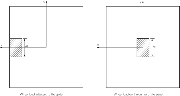
Figure 3.3.1 Diagrammatic illustration of wheel load location and size
Note The details shown in this figure are for illustration purposes only
Table 3.3.1 Tyre correction factor, n
| Number of wheels in idealised
patch
|
Pneumatic tyres
|
Solid rubber tyres
|
Steel or solid tyres
|
| 1
|
0,6
|
0,8
|
1,0
|
| 2 or more
|
0,75
|
0,9
|
1,0
|
Table 3.3.2 Curvature factor coefficients
truck wheel loads
| Aspect Ratio,
w/l
|
Short span, s, mm
|
t
n1, t
n2 mm
|
Coefficients
|
|
C
1
|
C
2
|
C
3
|
C
4
|
C
5
|
C
6
|
C
7
|
C
8
|
C
9
|
| Single
axle configuration, wheel load at center
|
|
w/l > 1,0
|
2000 ≤ s ≤ 2500
|
3
|
0,3
|
–0,2
|
8
|
150
|
0,04
|
–80
|
–35
|
130
|
–95
|
| 2000 ≤ s ≤ 3000
|
4,5
|
| 2000 ≤ s ≤ 3500
|
6,8,10
|
0,3
|
–0,2
|
8
|
150
|
0,04
|
–80
|
–35
|
130
|
–95
|
| 0,5 ≤ w/l
≤ 1,0
|
2000 ≤ s ≤ 2500
|
3
|
0,3
|
–0,2
|
8
|
150
|
0,04
|
–80
|
–
|
–
|
–
|
| 2000 ≤ s ≤ 3000
|
4,5
|
| 2000 ≤ s ≤ 3500
|
6,8,10
|
0,3
|
–0,2
|
8
|
150
|
0,04
|
–80
|
–
|
–
|
–
|
| Double
axle configuration, wheel load at center
|
|
w/l > 1,0
|
s = 2500
|
4
|
0
|
1,6
|
22
|
100
|
0,04
|
–100
|
–35
|
130
|
–95
|
| 2500 ≤ s ≤ 3000
|
5
|
| 2500 ≤ s ≤ 3500
|
6
|
0,3
|
0,4
|
8
|
180
|
0,04
|
–115
|
–45
|
165
|
–120
|
| 2500 ≤ s ≤ 3500
|
8
|
| 3000 ≤ s ≤ 3500
|
10
|
| 0,5 ≤ w/l ≤ 1,0
|
s = 2500
|
4
|
0
|
1,6
|
22
|
100
|
0,04
|
–100
|
–
|
–
|
–
|
| 2500 ≤
s ≤ 3000
|
5
|
| 2500 ≤
s ≤ 3500
|
6
|
0,3
|
0,4
|
8
|
180
|
0,04
|
–115
|
–
|
–
|
–
|
| 2500 ≤
s ≤ 3500
|
8
|
| 3000 ≤
s ≤ 3500
|
10
|
| Double
axle configuration, wheel load adjacent to transverse girder
|
|
w/l > 1,0
|
s = 2000
|
3
|
0,8
|
–1,5
|
5
|
140
|
0,06
|
–120
|
–35
|
130
|
–95
|
| 2000 ≤ s ≤ 2500
|
4
|
| 2000 ≤ s ≤ 3000
|
5
|
| 2000 ≤ s ≤ 3500
|
6
|
0,6
|
–0,3
|
–3
|
230
|
0,045
|
–130
|
–40
|
150
|
–110
|
| 2500 ≤ s ≤ 3500
|
8
|
| 3000 ≤ s ≤ 3500
|
10
|
0,8 ≤ w/l
≤ 1,0
use w/l = 0,8 if 0,5 ≤
w/l ≤ 0,8)
|
s = 2000
|
3
|
0,8
|
–1,5
|
5
|
140
|
0,06
|
–120
|
0
|
–50
|
50
|
| 2000 ≤
s ≤ 2500
|
4
|
| 2000 ≤
s ≤ 3000
|
5
|
| 2000 ≤
s ≤ 3500
|
6
|
0,6
|
–0,3
|
–3
|
230
|
0,045
|
–130
|
0
|
–50
|
50
|
| 2500 ≤
s ≤ 3500
|
8
|
| 3000 ≤
s ≤ 3500
|
10
|
Table 3.3.3 Curvature factor coefficients car
wheel loads
| Aspect Ratio,
w/l
|
Short span, s, mm
|
t
n1, t
n2 mm
|
Coefficients
|
|
C
1
|
C
2
|
C
3
|
C
4
|
C
5
|
C
6
|
C
7
|
C
8
|
C
9
|
| Single
axle configuration, wheel load at center
|
|
w/l > 1,0
|
2000 ≤
s ≤ 3000
|
3,4
|
0,2
|
0,4
|
25
|
200
|
0,04
|
–80
|
–50
|
185
|
–135
|
| 0,5 ≤
w/l ≤ 1,0
|
2000 ≤
s ≤ 3000
|
3,4
|
0,2
|
0,4
|
25
|
200
|
0,04
|
–80
|
–
|
–
|
–
|
3.2.5 Where decks are designed for the carriage of wheeled vehicles only or where the panels
are subjected to a distributed load in addition to the vehicle loading, the scantling
requirements are to be specially considered on the basis of direct calculation. The load
area is defined as the footprint of an individual wheel or the area enclosing a group of
wheels when the distance between footprints is less than the smaller dimension of the
individual prints. The structural design factor, fσ, is to be as required by
Pt 3, Ch 9 Special Features, Table 9.3.6 Structural design factors of the
.
3.2.6 The vehicles are to be positioned so as to produce the most severe loading condition for
each panel under consideration.
|