
Section
5 Castings for propellers
5.1 Scope
5.1.1 This Section
gives the requirements for steel castings for one-piece propellers
and separately cast blades and hubs for fixed pitch and controllable
pitch propellers (CPP). These include contra-rotating propellers,
azipods and azimuth thrusters. The requirements for copper alloy propellers,
blades and hubs are given in Ch 9, 1 Castings for propellers.
5.1.3 Full details
of the manufacturer's specification are to be submitted for approval.
These should include the chemical composition, heat treatment, mechanical
properties, microstructure and repair procedures.
5.2 Chemical composition
5.2.1 The chemical
composition of ladle samples is to comply with the approved specification, see
Ch 4, 5.1 Scope 5.1.3.
5.2.2 Typical cast steel propeller alloys are given in Table 4.5.1 Typical chemical composition for
steel propeller castings Cast steel whose chemical composition deviates from
the typical values of Table 4.5.1 Typical chemical composition for
steel propeller castings shall be specially approved by LR.
Table 4.5.1 Typical chemical composition for
steel propeller castings
| Alloy
type
|
C Max.
(%)
|
Mn
Max. (%)
|
Cr
(%)
|
Mo
Max. (%) (see Note)
|
Ni
(%)
|
Martensitic
(12Cr
1Ni)
|
0,15
|
2,0
|
11,5 – 17,0
|
0,5
|
Max. 2,0
|
Martensitic
(13Cr
4Ni)
|
0,06
|
2,0
|
11,5 – 17,0
|
1,0
|
3,5 – 5,0
|
Martensitic
(16Cr
5Ni)
|
0,06
|
2,0
|
15,0 – 17,5
|
1,5
|
3,5 – 6,0
|
Austenitic
(19Cr
11Ni)
|
0,12
|
1,6
|
16,0 – 21,0
|
4,0
|
8,0 – 13,0
|
Note Minimum values are to be in accordance with the agreed
specification or recognised National or International Standards.
|
5.3 Heat treatment
5.3.1 Martensitic
stainless steel castings are to be austenitised, quenched and tempered
in accordance with the approved specification, see
Ch 4, 5.1 Scope 5.1.3.
5.3.2 Austenitic
stainless steel castings are to be solution treated in accordance
with the approved specification, see
Ch 4, 5.1 Scope 5.1.3.
5.4 Mechanical tests
5.4.1 The test
material is to be cast integral with the boss of propeller castings,
or with the flange of separately cast propeller blades. Alternatively,
the test material may be attached on blades in an area between 0,5
and 0,6R, where R is the radius of the propeller.
5.4.2 The test
material is not to be removed from the casting until final heat treatment
has been carried out. Removal is to be by non-thermal procedures.
5.4.3 At least
one tensile test and for the martensitic stainless steel grades one
set of three Charpy V-notch impact tests are to be made on material
representing each casting. The results are to comply with the requirements
of Table 4.5.2 Typical mechanical properties for
steel propeller castings or the approved
specification.
Table 4.5.2 Typical mechanical properties for
steel propeller castings
| Alloy
type
|
Yield stress or, 0,2%
proof stress minimum, N/mm2
|
Tensile strength
minimum N/mm2
|
Elongation on 5,65  % minimum % minimum
|
Reduction of area %
minimum
|
Charpy V-notch impact
tests J minimum (see Notes 1 and 2)
|
| Martensitic
(12Cr 1Ni)
|
440
|
590
|
15
|
30
|
20
|
| Martensitic
(13Cr 4Ni)
|
550
|
750
|
15
|
35
|
30
|
| Martensitic
(16Cr 5Ni)
|
540
|
760
|
15
|
35
|
30
|
| Austenitic
(19Cr 11Ni)
|
180 (see Note 3)
|
440
|
30
|
40
|
-
|
Note
1. When a general service notation Ice
Class 1AS, 1A, 1B or 1C is required, the tests are to be made
at –10°C.
Note
2. For general service or where the
notation Ice Class 1D is required, the tests are to be made at
0°C.
Note
3.
R
p1,0 value is 205 N/mm2.
|
5.4.4 As an alternative
to Ch 4, 5.4 Mechanical tests 5.4.3, where a number of small
propeller castings of about the same size, and less than 1 m in diameter,
are made from one cast and heat treated together in the same furnace,
a batch testing procedure may be adopted using separately cast test
samples of suitable dimensions. At least one set of mechanical tests
is to be provided for each multiple of five castings in the batch.
5.4.5 Separately
cast test bars may be used subject to prior approval of the Surveyor.
Test bars must be cast from the same heat, or heats, and must also
be heat treated with castings they represent.
5.5 Quality of castings, inspection, and
Non-Destructive Examination
5.5.1 All finished castings are to be 100 per cent visually inspected by the manufacturer. A
comprehensive visual examination is to be carried out by the Surveyor.
5.5.2 Castings are to have a workmanlike finish and are to be free from cracks, hot tears, or
other imperfections which would be prejudicial to their proper application in
service.
5.5.3 Minor casting defects which may still be visible after machining such as small sand and
slag inclusions, small cold shuts and scabs are to be suitably removed by mechanical
means such as chipping or grinding.
5.5.5 For all propellers, separately cast blades, and hubs, the surfaces covered
by severity Zones A, B and C are to be subjected to penetrant testing, or magnetic
particle testing as appropriate to the material type. Testing of Zone A is to be
undertaken in the presence of the Surveyor, whilst testing of Zones B and C may be
witnessed by the Surveyor upon their request.
5.5.6 If repairs have been made either by grinding or by welding, the repaired
areas are additionally to be subjected to liquid testing (or magnetic particle testing,
as appropriate) independent of their location and/or severity zone. Weld repairs are,
independent of their location, always to be assessed according to Zone A.
5.5.8 The following definitions apply in relation to the assessment of
indications when using the penetrant testing method:
- An indication is defined as the presence of detectable
bleed-out of the penetrant liquid from the material discontinuities appearing at
least 10 minutes after the developer has been applied (see Note 1).
- Relevant indication: Only indications which have any
dimension greater than 1,5 mm shall be considered relevant for the categorisation
of indications.
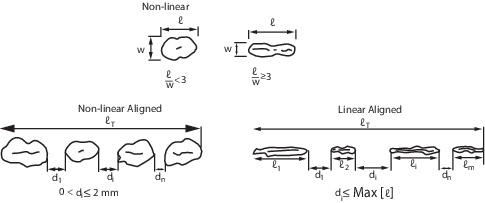
- Non-linear indication: an indication with a largest dimension
less than three times its smallest dimension (i.e. l < 3 w).
- Linear indication: an indication with a largest dimension
three or more times its smallest dimension (i.e. l ≥ 3 w).
- Aligned indications:
- Non-linear indications form an alignment when the
distance between indications is less than 2 mm and at least three
indications are aligned. An alignment of indications is considered to be a
unique indication and its length is equal to the overall length of the
alignment.
- Linear indications form an alignment when the distance
between two indications is smaller than the length of the longest
indication.
Note 1: Where there is uncertainty
regarding the dimensions of the bleed-out indication size, either due to a large number
of small, grouped indications, or an indication experiences excessive bleed-out, the
penetrant testing process shall be repeated by strictly following the procedure. In
exceptional circumstances, whereby the indication size cannot be accurately determined,
the actual discontinuity size may be further examined using visual inspection methods,
and augmented (if and where necessary) with the aid of magnification instruments, to
determine the actual size of the discontinuity, as visible on the surface of the
material.
5.5.9 This further examination is to be agreed with the Surveyor, and the Surveyor
may, where deemed necessary, request furtherNDE to ascertain the extent of indications,
which may include volumetric testing.
5.5.10 Where required by LR, or deemed necessary by the manufacturer and Surveyor, further
volumetric NDE (e.g. radiographic and/or ultrasonic testing) is to be carried out. The
acceptance criteria are to be agreed between the manufacturer and LR in accordance with
a recognised standard. Note: due to the attenuating effect of ultrasound within
austenitic steel castings, ultrasonic testing may not be effective in some cases,
depending on the shape/type/thickness, and grain-growth direction of the casting.
5.5.11 Advanced NDE methods, as described in Ch 1, 5.11 Advanced NDE methods, may be applied to
steel castings for propellers, as appropriate to the material type, thickness,
complexity and geometry, as a substitute for, or complementary to, conventional
ultrasonic or radiographic testing.
5.5.12 Static balancing is to be carried out on all propellers in accordance with the approved
drawing. Dynamic balancing may be necessary for propellers running above 500 rpm.
Table 4.5.3 Allowable number and size of
relevant indications in a reference area of 100 cm2(see
Note 1)
| Severity
Zones
|
Max. total
number of indications
|
Type of
indications (see Note 2)
|
Max. number of
each type (see Notes 3 and 4)
|
Max. acceptable
value for 'w' or 'l' of indications (mm) (see Note 2)
|
| A
|
7
|
Non-linear
|
5
|
4
|
|
|
|
Linear
|
2
|
3
|
|
|
|
Aligned
|
2
|
3
|
| B
|
14
|
Non-linear
|
10
|
6
|
|
|
|
Linear
|
4
|
6
|
|
|
|
Aligned
|
4
|
6
|
| C
|
20
|
Non-linear
|
14
|
8
|
|
|
|
Linear
|
6
|
6
|
|
|
|
Aligned
|
6
|
6
|
|
Note 1. The reference
area is defined as an area of 0,01 m2, which may be square
or rectangular, with the major dimension not exceeding 250 mm. The
area shall be taken in the most unfavourable location relative to the
indication being evaluated.
Note 2. Non-linear,
linear and aligned indications are defined as follows:
Note 3. Single non-linear
indications less than 2 mm in Zone A and less than 3 mm in other zones
are not considered relevant.
Note 4. The total number
of non-linear indications may be increased to the maximum total
number, or part thereof, represented by the absence of linear or
aligned indications.
|
5.6 Rectification of defective castings
5.6.2 Removal of defective material is to be by mechanical means, e.g. by
grinding, chipping or milling. The resultant grooves are to be blended into the
surrounding surface so as to avoid any sharp contours. Complete elimination of the
defect is to be verified by penetrant testing, or magnetic particle testing as
appropriate.
5.6.3 Grinding in severity Zone A may be carried out to an extent that maintains
the blade thickness. Repair by welding is generally not permitted in Zone A and will
only be allowed after special consideration.
5.6.4 Defects in severity Zone B that are not deeper than t/40 mm (t
is the minimum local thickness according to the Rules) or 2 mm, whichever is the
greater, are to be removed by grinding. Those defects that are deeper may be repaired by
welding subject to prior approval of the Surveyor.
5.6.5 Repair welding is generally permitted in severity Zone C.
5.6.7 Welding procedures are to be qualified in accordance with Ch 12, 3 Specific requirements for stainless steels with the following exceptions and
additions:
- Three macro specimens representing the start, middle, and end
of test weld are to be prepared and tested. The hardness readings are to be taken
from the macro specimen representing the start of weld.
- The mandrel diameter for bend test should be four times the
thickness of test specimen for martensitic stainless steel.
- The qualification range for base material thickness is given
in Table 4.5.4 Thickness approval range. The test assembly is to consist of cast
material and its thickness should be no less than 15 mm.
- The qualification is only valid for the base material grade
used for the test assembly.
- Approval for a test made in any position is restricted to
that position.
- The approval is only valid for the welding consumable trade
name used in the welding procedure test.
Table 4.5.4 Thickness approval range
| Test assembly
thickness, t (mm)
|
Thickness range
approved
|
| 15 < t ≤
30
|
3 mm to
3t
|
| t >30
mm
|
0,5t to
2t or 200 mm, whichever is greater
|
5.6.9 After weld repair, the propeller or blade is to be heat treated in such
fashion as will minimise the residual stresses. For martensitic stainless steels, this
will involve full heat treatment as specified in the approved specification. Special
consideration will be given to alternative heat treatment recommended by the
manufacturer.
5.6.10 LR reserves the right to restrict the amount of repair work accepted from a
manufacturer when it appears that repetitive defects are the result of improper foundry
techniques or practices.
5.7 Identification
5.7.1 Castings
are to be clearly marked by the manufacturer in accordance with the
requirements of Ch 1 General Requirements. The following
details are to be shown on all castings which have been accepted:
-
Identification mark
which will enable the full history of the item to be traced.
-
Type of steel, this
should include or allow identification of the chromium and nickel
contents.
-
LR or Clasifications Register
and the abbreviated name of Clasifications Register's local office.
-
Personal stamp of Surveyor
responsible for the final inspection.
-
LR certificate number.
-
Skew angle, if in excess
of 25°.
-
Ice class symbol, where
applicable.
-
Date of final inspection.
5.8 Certification of materials
5.8.1 In addition
to the requirements in Ch 4, 1.13 Certification of materials,
the manufacturer is to provide the Surveyor with a written statement
giving the following particulars for each casting:
-
Description of casting
with drawing number.
-
Diameter, number of
blades, pitch, direction of turning.
-
Skew angle, if in excess
of 25°
-
Final mass.
-
Vessel identification,
where known.
|