
Section
12 Closing arrangements for deck and shell
12.1 Hatch covers
12.1.1 The requirements
are given for single panel, steel plated or equivalent, cargo hatch
covers, stiffened longitudinally and secured around the perimeter
by manual ‘kestner’ type, clamping devices. The hatch
covers are, in general, lifted by a travelling gantry deck crane.
12.1.2 For hatch
covers of other types and designs, the scantlings will be specially
considered.
12.1.4 Where
hatch covers are manufactured from material other than steel, then
direct equivalency to these requirements is to be complied with.
12.2 Means to ensure weathertightness
12.2.1 The typical
weathertight sealing arrangement, in general, is achieved by a rubber
gasket on the hatch cover, compressed onto the top rail of the hatch
coaming, see
Figure 4.12.1 Typical hatch cover sealing arrangement.
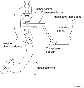
Figure 4.12.1 Typical hatch cover sealing arrangement
12.2.4 The clamping
devices may be cast or fabricated.
12.3 Plating
12.3.1 The thickness
of the plating of the hatch cover is to be not less than 6,0 mm or  , whichever is greater, where s is the spacing
of longitudinals or stiffeners (shorter panel dimension), in mm. , whichever is greater, where s is the spacing
of longitudinals or stiffeners (shorter panel dimension), in mm.
12.4 Stiffeners
12.4.1 The scantlings
and strength criteria of the hatch cover stiffeners are to be as follows:
-
For ships 110 m in length and greater, calculated with design loading
for Position 1, not less than 11,97 kN/m2and for Position 2, not less
than 9,52 kN/m2, with an equivalent design head of 1,70 m and 1,35 m
respectively. The product of the maximum stress thus calculated and the factor of
4,25 shall not exceed the minimum tensile strength of the material, with the
maximum permissible deflection limited to not more than 0,0028 times the span.
-
For ships 24,1 m in length, the design loading on the hatch cover for
Position 1, may be 9,52 kN/m2 and for Position 2, may be 7,16
kN/m2 with an equivalent design head of 1,35 m and 1,01 m
respectively.
-
For intermediate
lengths the values shall be obtained by linear interpolation.
The maximum permissible shear stress is not to exceed 108/k
Nmm2.
12.4.2 Additional
stiffening members are generally also arranged, so as to provide suitable
rigidity to the hatch cover during the lifting operation.
12.5 Hatch coamings
12.5.1 Hatch coamings, either vertical at sides or ends or sloped at sides, are to
have a minimum thickness of 11 mm. The top edge is to be stiffened by a horizontal flat
bar with a minimum width of 75 mm.
12.5.2 Additional support is to be given to the hatch coamings by the fitting of
stays not more than 3 m apart. Each stay is to have a minimum thickness of 9,5 mm and is
to be suitably supported under the deck.
12.5.3 Where
hatch side coamings are sloped, the support arrangements of the coaming
will be specially considered.
12.5.4 The deck
plating is generally to extend inside the coamings.
12.5.5 A hatch
end beam is to be arranged under the hatch end coaming. Transverse
continuation brackets are to be arranged outboard of the hatches in
line with the hatch end beam.
12.5.6 The height
of the coamings above the upper surface of the deck, for hatchways,
closed by covers secured weathertight by clamping devices shall be:
Position 1 (as defined in Ch 4, 1.4 Definitions 1.4.6)
– 460 mm
Position 2 (as defined in Ch 4, 1.4 Definitions 1.4.6) – 300 mm
12.5.7 Where
coamings of less height than required by 12.5.6 are fitted, the agreement
of the Canadian Authority shall be obtained and the requirements of Pt 3, Ch 11, 5.1 General 5.1.3 of the Rules
for Ships shall apply.
12.6 Engine room gangway doors
12.6.2 These
requirements cover cargo and service doors in the side shell plating
in way of the engine room.
12.6.3 Engine
room gangway doors shall be so fitted as to ensure tightness and structural
integrity commensurate with their location and the surrounding structure.
12.6.4 Without
the special agreement of the Canadian Authority, the lower edge of
the door openings shall not be below a line drawn parallel to the
freeboard deck at side, that has its lowest point at the upper edge
of the uppermost load line.
12.6.5 When
the doors open inward, the structure and closing arrangements will
be specially considered.
12.6.6 Where
an additional opening is arranged in the gangway door, then suitable
closing arrangements are to be fitted.
12.6.8 Doors
are to be fitted with an adequate means of closing, securing and support
so as to be commensurate with the strength and stiffness of the surrounding
structure. The hull supporting structure in way of the doors is to
be suitable for the same design loads and design stresses as the securing
and supporting devices. Where packing is required the packing material
is to be of a comparatively soft type and the supporting forces are
to be carried by the steel structure only. The maximum design clearance
between securing and supporting devices is generally not to exceed
3 mm.
|