
Section
3 Design
3.1 Fatigue strength analysis
3.1.1 As an alternative
to the following requirements, a fatigue strength analysis of components
can be submitted indicating a factor of safety of 1,5 at the design
loads, based on a suitable fatigue failure criteria. The effects of
stress concentrations, material properties and operating environment
are to be taken into account.
3.2 Intermediate shafts
3.2.1 The diameter, d, of the intermediate
shaft is to be not less than determined by the following formula:

|
k
|
= |
1,10 for shafts with keyways in tapered or cylindrical connections
where the fillet radii in the transverse section of the bottom of the keyway are
to be not less than 0,0125d |
|
F
|
= |
89 for electric propulsion installations |
|
F
|
= |
94 for engine installations |
P and R are defined in Pt 5, Ch 1, 3.3 Power ratings
(losses in gearboxes and bearings are to be disregarded)
After a length of 0,2d from the end of a keyway the diameter of
the shaft may be gradually reduced to that determined with k = 1,0.
3.2.2 For shrink
fit couplings k refers to the plain shaft section only. Where shafts
may experience vibratory stresses close to the permissible stresses
for continuous operation, an increase in diameter to the shrink fit
diameter is to be provided, e.g. a diameter increase of 1 to 2 per
cent and a blending radius as described in Pt 5, Ch 4, 3.7 Couplings and transitions of diameters 3.7.7.
3.2.3 Keyways
are in general not to be used in installations with a barred speed
range.
3.2.4 For shafts
with design features other than stated as above, the value of k will
be specially considered.
3.2.5 Carbon-manganese
steel intermediate shafts having flanges attached by fusion welding
may be accepted provided that the following conditions are complied
with:
-
The materials are
of a weldable quality with a carbon content generally not exceeding
0,23 per cent and the carbon equivalent not exceeding 0,4 per cent.
-
The weld is of a
full penetration type.
-
Welding is to be
in accordance with an LR approved procedure.
-
The welding is carried
out by qualified welders.
-
The shaft fillet
radius and flange are machined all over. Particular attention is to
be paid to the smooth blending of the fillet radius.
-
The welds are subsequently
examined by magnetic crack detection methods all to the Surveyor’s
satisfaction.
-
The shaft is to be
post-weld heat treated at a temperature of 650°C with a holding
time of one hour per 25 mm of weld thickness and thereafter allowing
the structure to cool slowly in the furnace.
-
The whole of the
work is carried out to the Surveyor’s satisfaction.
For a typical example of this type of coupling, see
Figure 4.3.1 Typical example of coupling welded to intermediate shaft. Alternative methods of
attaching the coupling flanges to intermediate shafts will be specially
considered.
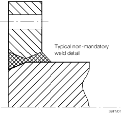
Figure 4.3.1 Typical example of coupling welded to intermediate shaft
3.3 Thrust shafts and thrust shaft bearing arrangements
3.3.1 Thrust
shafts and thrust shaft bearing arrangements situated outside the
gearbox or engine, with collar block arrangements or axial roller
thrust bearings, will be specially considered. For thrust shafts inside
the gearbox, see
Pt 5, Ch 3, 3.7 Design of enclosed gear shearing 3.7.8.
3.4 Screw shafts and tube shafts
3.4.2 The diameter, d
p of the protected screw shaft immediately forward of the forward face of the
propeller boss or, if applicable, the forward face of the screw shaft flange, is to be
not less than determined by the following formula:

where
|
k
|
= |
1,22 for a shaft carrying a keyless propeller fitted on a taper, or
where the propeller is attached to an integral flange, and where the shaft is oil
lubricated and provided with an approved type of oil sealing gland |
|
|
= |
1,26 for a shaft carrying a keyed propeller and where the shaft is
oil lubricated and provided with an approved type of oil sealing gland |
|
|
= |
P and R are defined in Pt 5, Ch 1, 3.3 Power ratings (losses in gearboxes and bearings are to be
disregarded) |
|
σu
|
= |
specified minimum tensile strength of the shaft material, in
N/mm2 but is not to be taken as greater than 600 N/mm2.
See
Pt 5, Ch 4, 2.1 Materials for shafts 2.1.3. |
3.4.3 The diameter, d
p of the screw shaft determined in accordance with
the formula in Pt 5, Ch 4, 3.4 Screw shafts and tube shafts 3.4.2 is to extend
over a length not less than that to the forward edge of the bearing
immediately forward of the propeller or 2,5d
p whichever
is the greater.
3.4.4 The diameter of the portion of the screw shaft and tube shaft, forward of
the length required by Pt 5, Ch 4, 3.4 Screw shafts and tube shafts 3.4.2 to the forward end of the forward sterntube seal, is
to be determined in accordance with the formula in Pt 5, Ch 4, 3.4 Screw shafts and tube shafts 3.4.2 with a k value of 1,15. The change of
diameter from that determined with k = 1,22 or 1,26 to that determined with
k = 1,15 should be gradual, see
Pt 5, Ch 4, 3.7 Couplings and transitions of diameters.
3.4.5 Screw shafts which run in sterntubes and tube shafts may have the diameter
forward of the forward sterntube seal gradually reduced to the diameter of the
intermediate shaft. Abrupt changes in shaft section at the screw shaft/tube shaft to
intermediate shaft couplings are to be avoided, see
Pt 5, Ch 4, 3.7 Couplings and transitions of diameters.
3.4.7 For shafts
of non-corrosion-resistant materials which are exposed to outboard
water, the diameter of the shaft is to be determined in accordance
with the formula in Pt 5, Ch 4, 3.4 Screw shafts and tube shafts 3.4.2 with
a k value of 1,26 and σu taken as 400
N/mm2.
3.5 Hollow shafts
3.5.1 Where the
thrust, intermediate, tube shafts and screw shafts have central holes,
having a diameter greater than 0,4 times the outside diameter, the
equivalent diameter d
e of a solid shaft is
not to be less than the Rule size, d, (of a solid shaft),
where d
e is given by:
where
|
d
o
|
= |
proposed outside diameter, in mm |
|
d
i
|
= |
diameter of central hole, in mm. |
3.5.2 Where the
diameter of the central hole does not exceed 0,4 times the outside
diameter, the diameter is to be calculated in accordance with the
appropriate requirements for a solid shaft.
3.6 Cardan shafts
3.6.1 Cardan
shafts, used in installations having more than one propulsion shaftline,
are to be of an approved design, suitable for the designed operating
conditions including short term high power operation. Consideration
will be given to accepting the use of approved cardan shafts in single
propulsion unit applications if a complete spare coupling is to be
provided on board.
3.6.2 Cardan
shaft ends are to be contained within substantial tubular guards that
also permit ready access for inspection and maintenance.
3.7 Couplings and transitions of diameters
3.7.1 The minimum
thicknesses of the coupling flanges are to be equal to the diameters
of the coupling bolts at the face of the couplings as required by Pt 5, Ch 4, 3.8 Coupling bolts 3.8.1, and for this purpose the minimum
tensile strength of the bolts is to be taken as equivalent to that
of the shafts. For intermediate shafts, thrust shafts and the inboard
end of the screwshaft, the thickness of the coupling flange is in
no case to be less than 0,20 of the diameter of the intermediate shaft
as required by Pt 5, Ch 4, 3.2 Intermediate shafts.
3.7.2 The fillet
radius at the base of the coupling flange is to be not less than 0,08
of the diameter of the shaft at the coupling. The fillets are to have
a smooth finish and are not to be recessed in way of nuts and bolt
heads.
3.7.3 Where the
propeller is attached by means of a flange, the thickness of the flange
is to be not less than 0,25 of the actual diameter of the adjacent
part of the screwshaft. The fillet radius at the base of the coupling
flange is to be not less than 0,125 of the diameter of the shaft at
the coupling.
3.7.4 All couplings
which are attached to shafts are to be of approved dimensions.
3.7.5 Where couplings
are separate from the shafts, provision is to be made to resist the
astern pull.
3.7.6 Where a
coupling is shrunk onto the parallel portion of a shaft or is mounted
on a slight taper, e.g. by means of the oil pressure injection method,
full particulars of the coupling including the interference fit are
to be submitted for special consideration.
3.7.7 Transitions
of diameters are to be designed with either a smooth taper or a blending
radius. In general a blending radius equal to the change in diameter
is recommended.
3.8 Coupling bolts
3.8.1 Close tolerance fitted bolts transmitting shear are to have a diameter,
d
b, at the flange joining faces of the couplings not less than:
|
d
b
|
= |

|
where
|
n
|
= |
number of bolts in the coupling |
|
D
|
= |
pitch circle diameter of bolts, in mm |
|
σu
|
= |
specified minimum tensile strength of bolts, in N/mm2
|
P and R are as defined in Pt 5, Ch 1, 3.3 Power ratings.
3.8.2 Where dowels
or expansion bolts are fitted to transmit torque in shear they are
to comply with the requirements of Pt 5, Ch 4, 3.8 Coupling bolts 3.8.1.
The expansion bolts are to be installed, and the bolt holes in the
flanges are to be correctly aligned in accordance with manufacturer's
instructions.
3.8.3 The minimum
diameter of tap bolts or of bolts in clearance holes at the joining
faces of coupling flanges, pretensioned to 70 per cent of the bolt
material yield strength value, is not to be less than:

where
d
R is taken as the
lesser of:
-
Mean of effective
(pitch) and minor diameters of the threads.
-
Bolt shank diameter
away from threads. (Not for waisted bolts which will be specially
considered.)
P and R are defined inPt 5, Ch 1, 3.3 Power ratings.
|
F
|
= |
2,5
where the flange connection is not accessible from within the ship
or vessel |
|
|
= |
2,0 where the flange
connection is accessible from within the ship or vessel |
|
C
|
= |
ratio
of vibratory/mean torque values at the rotational speed being considered |
|
D
|
= |
pitch
circle diameter of bolt holes, in mm |
|
Q
|
= |
external
load on bolt in N (+ve tensile load tending to separate flange, –ve) |
|
n
|
= |
number
of tap or clearance bolts |
|
σy
|
= |
bolt
material yield stress in N/mm2.
|
3.8.4 Consideration
will be given to those arrangements where the bolts are pre-tensioned
to loads other than 70 per cent of the material yield strength.
3.8.5 Where clamp bolts are fitted they are to comply with the requirements of
Pt 5, Ch 4, 3.8 Coupling bolts 3.8.3 and are to be installed, and the bolt holes in the
flanges correctly aligned, in accordance with manufacturer's instructions.
3.9 Keys and keyways for propeller connections
3.9.1 Round ended
or sled-runner ended keys are to be used, and the keyways in the propeller
boss and cone of the screwshaft are to be provided with a smooth fillet
at the bottom of the keyways. The radius of the fillet is to be at
least 0,0125 of the diameter of the screwshaft at the top of the cone.
The sharp edges at the top of the keyways are to be removed.
3.9.2 For sled-runner
ended keys at least one screwed pin is to be provided for securing
the key in the keyway, and the forward pin is to be placed at least
one-third of the length of the key from the end. The depth of the
tapped holes for the screwed pins is not to exceed the pin diameter,
and the edges of the holes are to be slightly bevelled.
3.9.3 The distance
between the top of the cone and the forward end of the keyway is to
be not less than 0,2 of the diameter of the screwshaft at the top
of the cone.
3.9.4 The effective
sectional area of the key in shear, is to be not less than:

where
|
d
|
= |
diameter,
in mm, required for the intermediate shaft determined in accordance
with Pt 5, Ch 4, 3.2 Intermediate shafts, based on material having
a specified minimum tensile strength of 400 N/mm2 and k =
1
|
|
d
1
|
= |
diameter of shaft at mid-length of the key, in mm |
|
σu
|
= |
specified
minimum tensile strength (UTS) of the key material, N/mm2.
|
3.9.5 The effective
area in crushing of key, shaft or boss is to be not less than:

where
|
σy
|
= |
yield
strength of key, shaft or boss material as appropriate, N/mm2.
|
3.10 Keys and keyways for inboard shaft connections
3.10.1 Round
ended keys are to be used and the keyways are to be provided with
a smooth fillet at the bottom of the keyways. The radius of the fillet
is to be at least 0,0125 of the diameter of the shaft at the coupling.
The sharp edges at the top of the keyways are to be removed.
3.10.2 The effective
area of the key in shear, A, is to be not less than:

where
|
d
|
= |
diameter,
in mm, required for the intermediate shaft determined in accordance
with Pt 5, Ch 4, 3.2 Intermediate shafts, based on material having
a specified minimum tensile strength of 400 N/mm2 and k= 1
|
|
d
1
|
= |
diameter of shaft at mid-length of the key, in mm |
|
σu
|
= |
specified
minimum tensile strength (UTS) of the key material, N/mm2.
|
3.11 Interference fit assemblies
3.11.1 The interference
fit assembly is to have a capacity to transmit a torque of S.Tmax without
slippage.
Note
For guidance purposes only,
Table 4.3.2 ‘C’ values for guidance
purposes
| Coupling location
|
C
|
| High speed shafting –
|
0,3
|
| I.C. engine driven
|
| High speed shafting
|
0,1
|
| Electric motor
driven
|
| Low speed shafting
–
|
0,1
|
| main or PTO stage
gearing
|
3.11.2 The effect
of any axial load acting on the assembly is to be considered.
3.11.3 The resulting
equivalent von Mises stress in the assembly is not to be greater than
the yield strength of the component material.
3.11.4 Reference
marks are to be provided on the adjacent surfaces of parts secured
by shrinkage alone.
3.12 Sternbushes and sterntube arrangement
3.12.1 Where
the sterntube or sternbushes are to be installed using a resin, of
an approved type, the following requirements are to be met:
-
Pouring and venting
holes are to be provided at opposite ends with the vent hole at the
highest point.
-
The minimum radial
gap occupied by the resin is to be not less than 6 mm at any one point
with a nominal resinthickness of 12 mm.
-
In the case of oil
lubricated sterntube bearings, the arrangement of the oil grooves
is to be such as to promote a positive circulation of oil in the bearing.
3.12.2 The length
of the bearing in the sternbush next to and supporting the propeller
is to be as follows:
-
For water lubricated bearings which are lined with ligum vitae, rubber
composition or staves of synthetic material, the length is to be not less than 4,0
times the rule diameter of the screwshaft in way of the bearing.
-
For water lubricated bearings lined with two or more
circumferentially spaced sectors or synthetic material, in which it can be shown
that the sectors operate on hydrodynamic principles, the length of the bearing is
to be such that the nominal bearing pressure will not exceed 0,55 MPa. The length
of the bearing is to be not less than 2,0 times the rule diameter of the shaft in
way of the bearing.
-
For oil lubricated bearings of synthetic material the length of the
bearing is, in general, to be not less than 2,0 times the rule diameter of the
shaft in way of the bearing. The nominal bearing pressure is not to exceed the
maximum for which the synthetic material has been approved
-
For bearings which are white-metal lined, oil lubricated and provided
with an approved type of oil sealing gland, the length of the bearing is to be
approximately 2,0 tmes the rule diameter of the shaft in way of the beairng and is
to be such that the nominal bearing pressure will not exceed 0,8 MPa. The length
of the bearing is to be not less than 1,5 times its diameter.
-
For bearings of cast iron and bronze which are oil lubricated and
fitted with an approved oil sealing gland, the length of the bearing is, in
general, to be not less than 4,0 times the rule diameter of the shaft in way of
the bearing.
-
For bearings which are grease lubricated, the length of the bearing
is to be not less than 4,0 times the rule diameter of the shaft in way of the
bearing. Other lengths may be considered upon application, subject to the
provision of suitable supporting in-service or testing evidence at relevant shaft
pressures and velocities.
3.12.4 Sternbushes
are to adequately secured in housings.
3.12.5 Forced water lubrication is to be provided for all bearings lined with
rubber or synthetic material. The supply of water may come from a circulating pump or
other pressure source. Flow indicators with an alarm in the wheelhouse are to be
provided for the water service to the bearings. The water grooves in the bearings are to
be of ample section and of a shape which will be little affected by weardown,
particularly for bearings of synthetic material.
3.12.7 Bearings
of synthetic material are to be supplied finished machined to design
dimensions within a rigid bush. Means are to be provided to prevent
rotation of the lining within the bush during operation.
3.12.8 The shut-off
valve or cock controlling the supply of water is to be fitted direct
to the after peak bulkhead, or to the sterntube where the water supply
enters the sterntube forward of the bulkhead.
3.12.9 Where
a tank supplying lubricating oil to the sternbush is fitted, it is
to be located above the load waterline and is to be provided with
a low level alarm device in the engine room.
3.12.10 Where
sternbush bearings are oil lubricated, provision is to be made for
cooling the oil by maintaining water in the after peak tank above
the level of the sterntube or by other approved means.
3.12.11 For oil lubricated bearings of synthetic material, the flow of lubricant is
to be such that overheating, under normal operating conditions, cannot occur.
3.12.12 Oil sealing glands must be capable of accommodating the effects of
differential expansion between hull and line of shafting for all water temperatures in
the proposed area of operation. This requirement applies particularly to those glands
which span the gap and maintain oil tightness between the sterntube and the propeller
boss.
3.12.13 Water
sealing glands must be capable of accommodating the effects of differential
expansion between hull and line of shafting for all water temperatures
in the proposed area of operation. Two independent sealing glands
are to be provided or alternatively one sealing gland capable of being
replaced when the ship is afloat.
3.13 Vibration and alignment
|