
Section
1 General
1.1 Application
1.1.1 The requirements
of this Chapter apply to the design and construction of piping systems,
including pipe fittings forming parts of such systems, including pipe
fittings forming parts of such systems, where the temperature does
not exceed 300°C.
1.1.3 The materials
used for pipes, valves and fittings are to be suitable for the medium
and the service for which the piping is intended.
1.2 Design symbols
1.2.1 The symbols
used in this Chapter are defined as follows:
|
a
|
= |
percentage
negative manufacturing tolerance on thickness |
|
c
|
= |
corrosion
allowance, in mm |
|
pt
|
= |
hydraulic test pressure, in MPa |
|
R
|
= |
radius
of curvature of a pipe bend at the centreline of the pipe, in mm |
|
t
|
= |
minimum
thickness of a straight pipe, in mm, including corrosion allowance
and negative tolerance where applicable |
|
t
b
|
= |
the minimum thickness of a straight pipe, in mm, to be used
for a pipe bend including bending allowance corrosion allowance and
negative tolerance, where applicable. |
|
σ |
= |
maximum permissible
design stress, in N/mm2.
|
1.2.2 The outside
diameter, D, is subject to manufacturing tolerances,
but these are not to be used in the evaluation of formulae.
1.2.3 The inside
diameter, d, is not to be confused with nominal pipe
size, which is an accepted designation associated with outside diameters
of standard rolling sizes.
1.2.4 The weld
efficiency factor, e, is to be taken as 1 for seamless
and electric resistance and induction welded steel pipes. Where other
methods of pipe manufacture are proposed, the value of e will
be specially considered.
1.3 Design pressure
1.3.1 The design
pressure, p, is the maximum permissible working pressure
and is to be not less than the highest set pressure of the safety
valve or relief valve.
1.3.2 In boiler
installations, the design pressure for steam piping is to be taken
as the design pressure of the boiler, i.e. not less than the highest
set pressure of any safety valve on the boiler.
1.3.3 The design
pressure of feed piping and other piping on the discharge from pumps
is to be taken as the pump pressure at full rated speed against a
shut valve. Where a safety valve or other protective device is fitted
to restrict the pressure to a lower value than the shut valve load,
the design pressure is to be the highest set pressure of the device.
1.4 Design temperature
1.4.1 The design
temperature is to be taken as the maximum temperature of the internal
fluid, but in no case is it to be less than 50°C.
1.5 Classes of pipes
1.5.1 Pressure
piping systems are divided into three classes for the purpose of assigning
appropriate testing requirements, type of joints to be adopted, heat
treatment and weld procedure.
1.5.2 Dependent
on the service for which they are intended, Class II and III pipes
are not to be used for design pressure or temperature conditions in
excess of those shown in Table 10.1.1 Maximum pressure and temperature
conditions for Class II and Class III piping systems.
Where either the maximum design pressure or temperature exceeds that
applicable to Class II pipes, Class I pipes are to be used. To illustrate
this, see
Figure 10.1.1 Classes of piping system. See also
Pt 5, Ch 10, 1.1 Application 1.1.2 for temperatures
exceeding 300°.
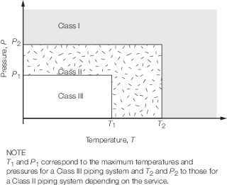
Figure 10.1.1 Classes of piping system
Table 10.1.1 Maximum pressure and temperature
conditions for Class II and Class III piping systems
| Piping
|
Class II
|
Class III
|
| system
|
p
|
T
|
p
|
T
|
|
|
MPa
|
°C
|
MPa
|
°C
|
| Steam
|
1,6
|
300
|
0,7
|
170
|
| Thermal oil
|
1,6
|
300
|
0,7
|
150
|
| Flammable
|
1,6
|
150
|
0,7
|
60
|
| liquids (see Note 1)
|
| Other media
|
4
|
300
|
1,6
|
200
|
| Cargo oil
|
4
|
300
|
1,6
|
200
|
Note
1. Flammable liquids include: fuel oil,
lubricating oil and flammable hydraulic oil.
|
1.6 Materials
1.6.1 Materials
for ferrous castings and forgings of Class I and Class II piping systems
are to be produced at works approved by Clasifications Register (hereinafter
referred to as 'LR') unless otherwise specifically mentioned in the
Rules. They are in general, to be tested in accordance with the
Rules for the Manufacture, Testing and Certification of Materials, July 2022
(hereinafter referred to as the Rules for
Materials).
1.6.2 The manufacturer's
test certificate for materials for pipes, valves and fittings of Class
I and Class II piping systems will be accepted in lieu of LR's materials
certificate where the maximum nominal pipe diameter is less than 50
mm or the product of working pressure in bar times nominal diameter
in mm is less than 2500. See
Ch 1, 3.1 General 3.1.3.(c) of the Rules for Materials.
1.6.3 For copper
alloys having a working temperature < 200°C, the manufacturer's
test certificate for materials for pipes, valves and fittings of Class
I and Class II piping systems will be accepted in lieu of LR's materials
certificate where the maximum nominal pipe diameter is less than 50
mm or the product of working pressure in bar times nominal diameter
in mm is less than 1500. See
Ch 1, 3.1 General 3.1.3.(c) of the Rules for Materials.
1.6.4 The manufacturer's
certificate for materials for ship-side valves and fittings and valves
on the collision bulkhead equal to or less than 500 mm nominal diameter
will be accepted in lieu of LR's materials certificate where the valves
and fittings are in accordance with a recognised National Standard
applicable to the intended application and are manufactured and tested
in accordance with the appropriate requirements of Ch 1, 3.1 General 3.1.3.(c) of the Rules for Materials.
|