
Section
11 Double skin structure
11.1 General
11.1.1 This
Section covers the arrangements and requirements for transversely
and longitudinally framed side shell structures of double skin ships.
11.1.3 The side
shell may be transversely or longitudinally framed. The longitudinal
bulkheads are in general to have the same framing system as the shell.
11.2 Transverse framing
11.2.1 The lower
ends of side frames and stiffeners of longitudinal bulkheads may overlap
the floors or otherwise be connected to the floors or tank top by
means of brackets. At their upper ends, side frames and bulkhead stiffeners
are to be interconnected by means of brackets, see
Figure 1.11.1 Frame arrangement (transverse framing).
11.2.2 In addition
to the frames, plate webs are to be fitted spaced not more than 8
m apart, see also
Figure 1.11.2 Arrangement of plate webs. Manhole openings are to be provided in the plate
webs to allow for inspection. Horizontal stiffeners are to be fitted
to the plate webs, spaced not more than twice the frame spacing apart.
Plate webs with large access holes are to be additionally stiffened
and their scantlings are to be verified by direct calculations. The
scantlings of truss-type web frames, replacing plate webs and composed
of rolled or built sections, are to be determined by direct calculation.
11.2.3 Alternatively,
plate webs in accordance with Pt 4, Ch 1, 11.2 Transverse framing 11.2.2 may
be fitted at every frame.
Table 1.11.1 Double skin structure (General
requirements)
| Item
|
Parameter
|
Requirement
|
| (1)
|
Shell frames
|
Modulus
|
 cm3 cm3
|
| (2)
|
Vertical stiffeners on longitudinal
bulkhead
|
Modulus
|

|
| (3)
|
Brackets under deck
|
Depth
|
db as shown in
Figure 1.11.1 Frame arrangement (transverse framing)
|
|
|
|
Thickness
|
 mm mm
|
|
|
|
Flange width
|
 mm mm
|
| Longitudinal framing systems
|
| (4)
|
Shell longitudinals
|
Modulus
|
 cm3, see Note 1 cm3, see Note 1
|
| (5)
|
Horizontal stiffeners on longitudinal
bulkhead
|
Modulus
|
 cm3, see Note 1 cm3, see Note 1
|
| (6)
|
Web frames at shell, see
Figure 1.11.3 Arrangement for web frames
|
Modulus
|
 cm3 cm3
|
| (7)
|
Web frames on longitudinal bulkhead,
Figure 1.11.3 Arrangement for web frames
|
Modulus
|

|
| (8)
|
Bracket under deck
|
Depth
|
dbas shown in Figure 1.11.1 Frame arrangement (transverse framing)
|
|
|
|
Thickness
|
 mm mm
|
|
|
|
Flange width
|
 m m
|
| Transverse and longitudinal framing systems
|
| (9)
|
Plating of longitudinal bulkhead,
see Notes 2 and 3
|
Thickness
|

|
| (10)
|
Plate webs, see
Figure 1.11.2 Arrangement of plate webs
|
Thickness
|
The greater of
 mm mm


|
| (11)
|
Horizontal stiffeners on webs
|
Width
|
 mm mm
|
|
|
|
Thickness
|
 thickness plate webs thickness plate webs
|
| Symbols
|
| L,
B, D, T, S, s, t, k,
Z and Iare as defined in Pt 4, Ch 1, 1.5 Symbols and definitions 1.5.1
|
|
hs
|
= |
hde + ht but not less than 2,0
m |
|
hde
|
= |
distance of longitudinal to the deck at side, in
metres |
|
|
= |
0,50 for deep tanks but not less than the distance to
the top of the overflow |
|
s1
|
= |
spacing between horizontal stiffeners, in metres |
|
sd
|
= |
stiffener spacing or width of double skin, whichever
is the smaller |
|
|
ts
|
= |
thickness of side shell, in mm |
|
L1
|
= |
L, but is to be taken as not less than 50 m nor more than
100 m |
|
Sb
|
= |
spacing of plate webs, in metres |
|
h4 |
= |
ho + 0,5 b1 |
| = |
the greater of the distance, in metres, from the middle of the
effective length to the top of the cargo or |
| = |
1,5 m |
| = |
whichever is the greatest |
|
hO |
= |
the vertical distance, in metres, from the mid-point of span of
the stiffener to the highest point of the tank including
hatchway |
|
b1 |
= |
the horizontal distance, in metres, from the centre line to the
hatchway in way of the cargo hatch |
|
T1
|
= |
D – q, but need be taken not greater than T +
0,4 – q for Zone 3, T + 0,7 – q m for Zone 2, T + 1,0 – q m
for Zone 1, in metres |
|
Zf
|
= |
modulus of frame, in cm3
|
|
Zl
|
= |
modulus of side shell longitudinal, in cm3
|
|
Zw
|
= |
modulus of web frame, in cm3
|
|
Note
1. The web thickness of longitudinals is
not to be less than 7 mm.
Note
2. For bulk carriers it is recommended to
add 3 mm to the thickness of the lower edge of the bulkhead over a
height of about 250 mm above the inner bottom.
Note
3. The thickness of the upper strake of
the longitudinal bulkhead may require to be increased to satisfy the
hull girder bending stress criteria in Pt 3, Ch 4 Longitudinal Strength
|
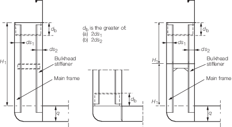
Figure 1.11.1 Frame arrangement (transverse framing)
11.3 Longitudinal framing
11.3.1 Longitudinals
on shell and longitudinal bulkheads are to be supported by web frames,
spaced not more than 2,5 m apart, and efficiently connected thereto.
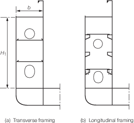
Figure 1.11.2 Arrangement of plate webs
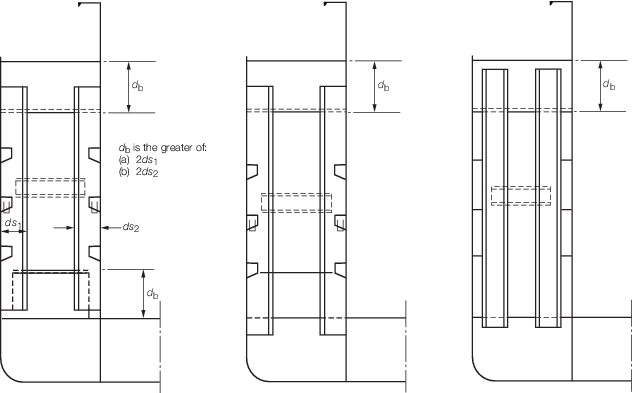
Figure 1.11.3 Arrangement for web frames
11.3.2 Web frames
are to be fitted in line with plate floors and are generally to be
constructed as indicated in Figure 1.11.3 Arrangement for web frames.
The lower ends of the web frames may overlap the floors or are otherwise
to be connected to the floors or tank top by means of brackets. At
their upper ends, web frames are to be interconnected by means of
brackets, see also
Figure 1.11.3 Arrangement for web frames.
11.3.3 In addition
to the web frames as required by Pt 4, Ch 1, 11.3 Longitudinal framing 11.3.2,
plate webs are to be fitted not more than 8 m apart, see also Fig. Figure 1.11.2 Arrangement of plate webs(b). Manhole openings are to
be provided in the plate webs to allow for inspection. Horizontal
stiffeners are to be fitted to the plate webs spaced not more than
twice the frame spacing apart. Plate webs with large access holes
are to be additionally stiffened and their scantlings are to be verified
by direct calculations.
11.4 Longitudinal bulkhead
11.4.2 Where
the longitudinal bulkhead is not connected to the bottom shell but
supported by the bottom floors, vertical stiffeners are to be fitted
to the floors and connected to the inner bottom plating in line with
the longitudinal bulkhead.
11.4.3 The ends
of the longitudinal bulkheads are to be well scarfed into the ship's
fore and aft structure.
11.5 Watertight sub-division
11.5.1 It is
recommended that Owners consider subdividing the space between side
shell and longitudinal bulkhead such that the ship remains afloat
when one of the compartments becomes flooded.
11.5.2 For ships navigating on the Rhine or on European waterways with an overall
length greater than 110 m, compliance with damage stability requirements are mandatory
in accordance with the European Standard laying down Technical Requirements for Inland
Navigation vessels (ES-TRIN).
|