
Section
10 Single side shell and deck supporting structure
10.1 General
10.1.1 This
Section covers the arrangements and requirements for one of the following
transverse framing systems:
-
Support of the side
shell and deck by framing of equal profile depth only.
-
Support of the side
shell and deck by a combination of frames and web frames or bulkheads.
10.1.2 The scantlings
of the side shell structural parts, viz. frames, web
frames and the brackets under deck from frame to coaming are to comply
with Table 1.10.1 Single skin construction.
10.1.3 Where
a longitudinal framing system is adopted, the scantlings and arrangements
will be specially considered.
10.2 Frames
10.2.1 In ships
with a single bottom, the lower end of the frames is to overlap the
floors. In ships with a double bottom, the lower end of the frame
is to be efficiently connected to the double bottom structure.
10.3 Web frames
10.4 Brackets under deck
10.4.1 At the
head of frames and web frames, brackets are to be fitted supporting
deck and hatch coaming. The arrangements of the brackets is shown
in Figure 1.10.1 Frame arrangement. The scantlings
of the brackets at the frames and web frames are to have equal dimensions,
it being assumed that the load from coaming and deck is evenly distributed
over each bracket. Proposals for other structural arrangements resulting
in a different distribution of loads will be specially considered.
Where a travelling crane for the lifting of hatch covers or cargo
is used, the load from the crane is also to be taken into account
when calculating the bracket scantlings.
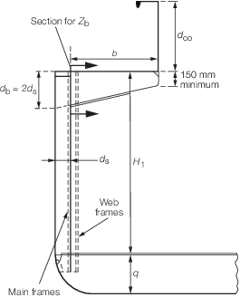
Figure 1.10.1 Frame arrangement
Table 1.10.1 Single skin construction
| Item
|
Parameter
|
Requirement
|
| (1) Frames
|
Modulus
|
 cm3 cm3
|
| (2) Web frames
|
Modulus
|

|
| (3) Brackets under
deck
|
Depth
|
d
b = as shown in Figure 1.10.1 Frame arrangement
|
| Thickness
|

|
| Flange width
|
b
f = 70 mm minimum
|
| Minimum required
modulus
|
Zb = 29k x k
2 x b x s (b x h
1 + b
1 x h
h) cm3
|
| Symbols
|
|
D, T, S, s, t, k and z
are as defined in Pt 4, Ch 1, 1.5 Symbols and definitions 1.5.1
|
b
|
= |
width of bracket, in metres, as shown in Figure 1.10.1 Frame arrangement
|
|
bf
|
= |
width of bracket flange, in mm |
|
b1
|
= |
width of hatchway, in metres |
|
hh
|
= |
head, in metres, on the hatch covers (if fitted) as
defined in Pt 3, Ch 3, 4 Design loading
|
|
h1
|
= |
head on deck, in metres, as defined in Pt 3, Ch 3, 4 Design loading
|
|
k1
|
= |
1 + (u – 15) x 0,078, but this factor is to be
not less than 1, nor greater than 3,33, where |
|
u
|
= |
distance between transverse bulkheads, web frames or
other efficient transverse supports, in metres |
|
k2
|
= |
L
co/12d
co – 1, but this factor is to be taken not less than 0,
nor greater than 1, where |
|
Lco
|
= |
length of hatch coaming between transverse bulkheads,
or other efficient vertical supports, in metres |
|
dco
|
= |
depth of hatch coaming, in metres, as shown in Figure 1.10.1 Frame arrangement
|
|
q |
= |
height of single or double bottom, in metres, as
shown in Figure 1.10.1 Frame arrangement
|
|
H1
|
= |
vertical framing depth, in metres, as shown in Figure 1.10.1 Frame arrangement
|
|
T1
|
= |
D – q but need not be taken greater than T +
0,4 – q for Zone 3, T + 0,7 – q for Zone 2,
T + 1,0 – q for Zone 1, in metres |
|
Zb
|
= |
modulus, in cm3, of brackets under deck at
the intersection with the frame as indicated in Figure 1.10.1 Frame arrangement
|
|
Zf
|
= |
modulus of the frame, in cm3
|
|
Note
1. Where frames do not support cantilever
brackets under deck, a minimum value of 15 cm3 for
Zb is to be applied.
Note
2.
Zb is to be obtained from (3) taking
k2= 1 and s as the spacing between web
frames
Note
3. If the factor k2 is
0, the frame bracket may also be replaced by a deck beam with a
section modulus not less than half the section modulus of a frame and
suitably connected to the frame.
|
|
| Copyright 2022 Clasifications Register Group Limited, International Maritime Organization, International Labour Organization or Maritime
and Coastguard Agency. All rights reserved. Clasifications Register Group Limited, its affiliates and subsidiaries and their respective
officers, employees or agents are, individually and collectively, referred to in this clause as 'Clasifications Register'. Clasifications
Register assumes no responsibility and shall not be liable to any person for any loss, damage or expense caused by reliance
on the information or advice in this document or howsoever provided, unless that person has signed a contract with the relevant
Clasifications Register entity for the provision of this information or advice and in that case any responsibility or liability is
exclusively on the terms and conditions set out in that contract.
|
 |
|