
Section
2 Decks loaded by wheeled vehicles
2.1 General
2.1.1 Where it
is proposed either to stow wheeled vehicles on the deck or to use
wheeled vehicles for cargo handling, the deck and supporting structure
are to be designed on the basis of the maximum loading to which they
may be subjected in service. Where applicable, hatch covers are to
be similarly designed. In no case, however, are the scantlings to
be less than would be required for a deck in this location.
2.2 Loading
2.2.1 Details
of the deck loading resulting from the proposed stowage or operation
of vehicles are to be supplied by the Shipbuilder. These details are
to include the wheel load, axle and wheel spacing, tyre print dimensions
and type of tyre for the vehicles.
2.2.2 For design
purposes where wheeled vehicles are to be used for cargo handling,
the deck is to be taken as loaded with a normal head of cargo, except
in way of the vehicle.
2.3 Deck plating
2.3.1 The deck
plating thickness is to comply with Table 9.2.1 Loading by wheeled
vehicles.
Table 9.2.1 Loading by wheeled
vehicles
| Item
|
Parameter
|
Requirements
|
|
(1) Deck plating
|
Plating thickness
|
|
t
|
= |
 + 1,5 mm, see Note + 1,5 mm, see Note |
|
|
(2) Deck beams, longitudinals and stiffeners when fork lift
trucks are to be used
|
Section modulus
|
|
Z
|
= |
(0,375K
1
Ple + 1,25K
2
hsle
2 )k cm3
|
|
|
(3) Deck beams, longitudinals and stiffeners for decks
permanently used for vehicles, in association with a value of h
which need not exceed 2,5 m
|
Section modulus
|
|
Z
|
= |
(0,536K
1
Ple + 1,25K
2
hsle
2)k cm3
|
|
|
(4) Deck girders and transverses
|
Section modulus
|
|
| Symbols
|
|
b
|
= |
mean width of plating supported by a deck girder or
transverse, in metres |
|
s
|
= |
spacing of stiffeners, in metres |
|
t
|
= |
thickness of plating, in mm |
K
1 and K
2 are factors given in Table 9.2.4 Values of K
1 and K
2
|
P
|
= |
total weight of the vehicle divided by the number of
axles. Where the distribution of weight is not uniform, P is
to be taken as the maximum axle load. For fork lift trucks the
total weight is to be applied to one axle, in tonnes |
|
|
|
Table 9.2.2 Corrected patch load
calculation
| Symbols
|
Expression
|
a, s, u and v
are as defined inFigure 9.2.1 Tyre print load stress
factor
|
P
1
|
= |
corrected patch load, in tonnes |
|
Φ1
|
= |
patch aspect ratio correction factor |
|
Φ2
|
= |
panel aspect ratio correction factor |
|
Φ3
|
= |
wide patch load factor |
|
|
|
Φ1 |
= |

|
|
v
1 = v, but ≤ s
u
1 = u, but ≤ a
|
|
|
for u ≤ (a - s)
|
|
|
= |

|
|
for a ≥ u >
(a – s)
|
|
|
= |
0,77
|
|
for u > a
|
|
|
for v < s
|
|
|
= |
0,6 + 0,4 + 0,4 |
|
for 1,5 >  > 1,0 > 1,0
|
|
|
= |
1,2
|
|
for  ≥ 1,5 ≥ 1,5
|
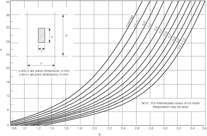
Figure 9.2.1 Tyre print load stress
factor
Table 9.2.3 Approximate deck thickness for
fork lift trucks
| Capacity of fork lift,
in tonnes
|
 (max.) (max.)
|
| 1,0
|
0,085
|
| 5,0
|
0,045
|
| 10,0
|
0,037
|
| 15,0
|
0,034
|
| 20,0
|
0,032
|
Table 9.2.4 Values of K
1 and K
2

|
K
1
|
K
2
|
| 0,1
|
15,4
|
1,89
|
| 0,2
|
14,6
|
1,845
|
| 0,3
|
13,35
|
1,730
|
| 0,4
|
11,8
|
1,55
|
| 0,5 and greater
|
10,1
|
1,30
|
| *Outer
wheel to outer wheel on axles with multiple wheel arrangements
|
2.3.3 Where it
is proposed to use vehicles having steel wheels, deck thicknesses
will be specially considered.
2.3.4 Where transversely
framed decks contribute to the hull girder strength or where secondary
stiffening is fitted perpendicular to the direction of vehicle lanes,
the thickness, t, derived from Table 9.2.1 Loading by wheeled
vehicles is to be increased by 1,0 mm.
2.3.5 Where decks
are designed for the exclusive carriage of unladen wheeled vehicles,
the deck plate thickness, t, derived from Table 9.2.1 Loading by wheeled
vehicles may be reduced by 0,75
mm.
2.3.6 Where it
is proposed to carry tracked vehicles, the patch dimensions may be
taken as the track print dimensions and P
w is
to be taken as half the total weight of the vehicle. The deckplate
thickness, t, derived from Table 9.2.1 Loading by wheeled
vehicles is to be increased by 0,5 mm. Deck fittings in way of
vehicle lanes are to be recessed.
2.3.7 If wheeled
vehicles are to be used on insulated decks or tanktops, consideration
will be given to the permissible loading in association with the insulation
arrangements and the plating thickness.
2.4 Deck beams and longitudinals
2.4.1 The section
modulus, Z, of deck beams or longitudinals is to be not
less than that required for a deck in this location, nor less than
the following:
-
For general purpose
cargo decks where fork lift trucks are to be used, the value of Z is
to be as in Table 9.2.1 Loading by wheeled
vehicles.
-
For permanent vehicle
decks in association with a value of h which need not
exceed 2,5 m, Z is to be as in Table 9.2.1 Loading by wheeled
vehicles.
-
For decks designed
for the carriage of wheeled vehicles only:
that required to satisfy the most severe arrangement of print
wheel loads on the stiffener in association with a bending stress
of 100 N/mm2 (10,2 kgf/mm2) assuming 100 per
cent end fixity.
2.5 Deck girders and transverses
2.5.2 Where the
member supports point loads, with or without the addition of uniformly
distributed load, the section modulus is to be based on a stress of
123,6 N/mm2 (12,6 kgf/mm2) assuming 100 per
cent end fixity.
2.5.3 Where it
is proposed to carry tracked vehicles, the total weight of the vehicle
is to be taken when determining the section modulus of the transverse
at the top of a ramp or at other changes of gradient.
2.6 Heavy and special loads
2.6.1 Where heavy
or special loads, such as machinery transporters or large tracked
vehicles are proposed to be carried, the scantlings and arrangements
of the deck structure will be individually considered.
|