
Section
2 Scantlings of bulkheads
2.1 Watertight and deep tank bulkheads
2.1.2 Stiffening
members of horizontal bulkheads of tanks may be supported by girders
or a system of girders and pillars.
Table 7.2.1 Watertight and deep tank bulkhead
scantlings
| Item and
requirement
|
Watertight
bulkheads
|
Deep tank
bulkheads
|
|
(1) Plating thickness for plane and symmetrically corrugated
bulkheads
|
The greater of the following:
|
t
|
= |
4w
 + 0,5 mm + 0,5 mm |
or
|
The greater of the following:
|
t
|
= |
4w  + a mm + a mm |
or
|
t
|
= |
5 mm for oil tanks and fresh water tanks |
|
t
|
= |
5,5 mm for water ballast tanks, see Note 3 |
|
|
(2) Modulus of rolled and built stiffeners, swedges and
symmetrical corrugations
|
|
Z
|
= |
5 × k × s × le
2 × h
4 cm3
|
|
|
Z
|
= |
6 × k × s × le
2 × h
4 × ρ cm3
|
|
|
(3) Stringers or webs supporting vertical or horizontal
stiffening
|
|
|
|
(a) Modulus
|
|
Z
|
= |
7 × k × h
4 × S × le
2 cm3
|
|
|
Z
|
= |
8,5 × k× h
4 × S × le
2 × ρ cm3
|
|
|
(b) Inertia
|
-
|
|
|
= |
 cm4 cm4
|
|
|
(4) Pillars in tanks, cross-sectional area
|
-
|
|
| Symbols
|
|
t
|
= |
thickness of plating, in mm |
|
s
|
= |
spacing of stiffeners, corrugations, girders or webs,
in metres |
|
ρ |
= |
specific gravity of liquid carried in the tank, but
is to be taken as not less than 1 |
|
a
|
= |
1 mm for oil and fresh water tanks and 1,5 mm for
water ballast tanks |
|
h
4
|
= |
load head, in metres, measured vertically as follows,
see also
Figure 7.2.1 Heads for watertight and deep tank bulkheads
- (a) for vertically stiffened watertight bulkhead plating –
the distance from a point 0,5 m above the lower edge of the
plate to the top of the bulkhead
- (b) for horizontally stiffened watertight bulkhead plating
- the distance from the middle of the first panel above the
lower edge of the plate to the top of the bulkhead
- (c) for vertically stiffened deep tank bulkhead plating -
the distance from a point 0,5 m above the lower edge of the
plate to a point 1 m above the top of the tank, or to the top
of the overflow, whichever is the greater
- (d) for horizontally stiffened deep tank bulkhead plating -
the distance from the middle of the first panel above the
lower edge of the plate to a point 1 m above the top of the
tank, or to the top of the overflow, whichever is the
greater
- (e) for watertight stiffeners or girders, the distance from
the middle of the effective length to the top of the
bulkhead
- (f) for deep tank bulkhead stiffeners or girders, the
distance from the middle of the effective length to a point 1
m above the top of the tank, or to the top of the overflow,
whichever is the greater
|
|
P
|
= |
load supported by the pillars, in tonne f |
|
Note
1. For rolled or built stiffeners with
flanges for face plates the web thickness is to be not less than  of the web depth, whilst for flat bar stiffeners
the web thickness is to be not less than of the web depth, whilst for flat bar stiffeners
the web thickness is to be not less than  of the web depth. of the web depth.
Note
3. Bulkhead plating from the bottom to
0,1 m above ceiling in holds is to be at least 6 mm in thickness.
|
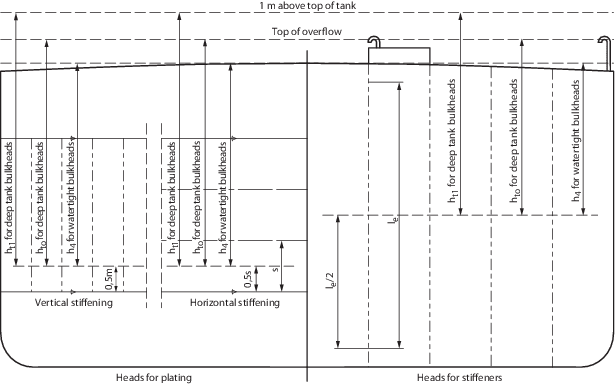
Figure 7.2.1 Heads for watertight and deep tank bulkheads
2.1.3 Pillars
in tanks are not to be of hollow construction and are to be bracketed
at top and bottom. Scantlings and welding of the brackets are to take
account of the maximum tensile force on the pillar.
2.1.5 Fuel oil
carried in tanks is to have a flash point not less than 55°C.
Where tanks are intended for liquid fuels of a special nature, the
scantlings and arrangements will be considered in relation to the
nature of the fuel, see also
Pt 3, Ch 12, 2 Rudders.
2.1.6 If cargo
is carried in a compartment adjacent to a fuel oil tank which may
be heated, the compartment side of the bulkhead or deck is to be insulated,
or equivalent arrangements provided.
2.1.7 Where watertight
bulkhead stiffeners are cut in way of watertight doors, the opening
is to be suitably framed and reinforced, and the adjacent stiffeners
are to be increased in proportion to the greater spacing. Where the
stiffener spacing is locally increased on account of watertight doors,
the stiffeners at the sides of the doorways are also to be increased.
Recesses in bulkheads are generally to be so stiffened as to provide
strength and stiffness equivalent to the requirements for the bulkhead.
2.2 Non-watertight bulkheads
2.2.1 The scantlings
of non-watertight bulkheads acting as hull supporting structure are
to comply with the requirements of Table 7.2.2 Non-watertight bulkheads. Where the bulkhead stiffeners support deck girders,
transverses or pillars over, they are also to comply with the requirements
of Table 7.2.3 Bulkhead stiffeners supporting
concentrated loads.
Table 7.2.2 Non-watertight bulkheads
| Parameter
|
Requirements
|
| (1) Plating thickness for plane
bulkheads
|
The greater of the following:
t = 4 × k × s ×  mm mm
or
t = 3,5 mm
|
| (2) Modulus of rolled and built
stiffeners and swedges
|
Z = 4 × k × s ×
le
2 × h
4 + 3 cm3
|
|
|
Table 7.2.3 Bulkhead stiffeners supporting
concentrated loads
| Parameter
|
Requirements
|
| (1) Cross-sectional area for rolled,
built or swedged stiffeners, supporting girders, transverses, pillars or
concentrated loads
|
see Note
|
| (2) Width of effective plating
included in the cross-sectional area
|
The lesser of the following
w = 80t mm
or
w = 700s mm
|
| Symbols
|
|
|
|
|
|
|
|
r
|
= |
least radius of gyration of stiffener with effective
plating, in mm, and is to be taken as: 
|
|
|
s
|
= |
spacing of stiffeners, in metres, but not to exceed
1,10 m |
|
|
t
|
= |
thickness of plating, in mm |
|
|
w
|
= |
width of effective plating, in mm |
|
|
A
|
= |
cross-sectional area of stiffening member inclusive of
effective plating, in cm2
|
|
|
Ip
|
= |
least moment of inertia of stiffener with effective
plating, in cm4
|
|
|
P
|
= |
load supported by stiffener, in tonne-f |
|
|
|
Note The depth of stiffeners supporting concentrated loads is
to be not less than 75 mm.
|
2.3 Bulkheads in cargo spaces
2.3.1 Bulkheads
in cargo holds which are regularly exposed to contact with grabs or
falling cargo are to be efficiently protected or the scantlings increased
in order to reduce damage.
|