
Section
2 Welding
2.1 General
2.1.1 Details
of the welded connections of main structural members, including type
and size of welds, are to be clearly indicated on the plans submitted
for approval. This includes welded connections to steel castings.
The extent to which automatic welding is used should be indicated.
2.1.2 Unless
otherwise indicated, all welding is to be in accordance with the requirements
of Ch 13 Requirements for Welded Construction of the Rules for
the Manufacture, Testing and Certification of Materials (hereinafter
referred to as the Rules for Materials).
2.2 Fillet welds
2.2.1 The throat
thickness of fillet welds is to be determined from:
|
Throat thickness |
= |
t
p x weld factor x 
|
where
|
d
|
= |
the
distance between start positions of successive weld fillet, in mm |
|
s
|
= |
the
length, in mm, of correctly proportioned weld fillet, clear of end
craters, and is to be not less than 75 mm |
|
t
p
|
= |
plate thickness, on which weld fillet size is based, in mm |
see also
Figure 10.2.1 Weld types.
Weld factors are given in Table 10.2.1 Weld factors and Table 10.2.2 Throat thickness limits.
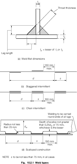
Figure 10.2.1 Weld types
Table 10.2.1 Weld factors
| Item
|
Weld
factor
|
Remarks
|
| (1)
|
General application:
|
|
except as required
below
|
|
|
Watertight plate boundaries
|
0,34
|
|
|
|
Non-tight plate boundaries
|
0,13
|
|
|
|
Longitudinals, frames, beams, and other secondary
members to shell, deck or bulkhead plating
|
0,10
0,13
0,21
|
in tanks
in way of end connections
|
|
|
Panel stiffeners, etc.
|
0,10
|
|
|
|
Overlap welds generally
|
0,27
|
|
| (2)
|
Bottom construction in way of holds or tanks:
|
|
|
|
|
Non-tight centre girder : to keel
|
0,27
|
|
|
|
to inner bottom
|
0,21
|
no scallops
|
|
|
Non-tight boundaries of floors, girders and brackets
|
0,21
0,27
|
in way of 0,2 x span at ends
in way of brackets at lower end of main frame
|
|
|
Watertight bottom girders
|
0,34
|
|
|
|
Connection of girder to inner bottom in way of longitudinal
bulkheads supported on inner bottom
|
0,44
|
|
|
|
Inner bottom longitudinals or reverse frames
|
0,13
|
under holds strengthened
for heavy cargoes
|
|
|
Connection of floors to inner bottom in way of plane bulkheads or
corrugated and double plate bulkheads supported on inner bottom. The
supporting floors are to be continuously welded to the inner bottom
|
0,44
|
Weld size based on floor
thickness
Weld material compatible with floor
material
|
| (3)
|
Hull framing:
|
|
|
|
|
Webs of web frames and stringers:
|
|
|
|
|
|
to shell
|
0,16
|
|
|
|
|
to face
plate
|
0,13
|
|
|
|
Tank side brackets to shell and inner bottom
|
0,34
|
|
| (4)
|
Decks and supporting structure:
|
|
|
|
|
Strength deck plating to shell
|
|
as shown in Table 10.2.5 Weld connection of strength deck
plating to sheerstrake but alternative proposals will be
considered
|
|
|
Other decks to shell and bulkheads (except where forming tank
boundaries)
|
0,21
|
generally
continuous
|
|
|
Webs of cantilevers to deck and to shell in way of root
bracket
|
0,44
|
|
|
|
Webs of cantilevers to face plate
|
0,21
|
|
|
|
Pillars: fabricated
end connections
end connections (tubular)
|
0,10
0,34
full penetration
|
see Note 1
|
|
|
Girder web connections and brackets in way of pillar heads and
heels
|
0,21
|
continuous
|
| (5)
|
Bulkheads and tank construction:
|
|
|
|
|
Plane, double plate and corrugated
watertight
bulkhead boundary at bottom, bilge,
inner
bottom and deck
|
0,44
|
weld size to be based on
thickness of bulkhead plating
weld material to be compatible
with bulkhead plating material
|
|
|
Boundary at bottom, bilge, inner bottom and deck
|
0,44
|
|
|
|
Secondary members where acting as pillars
|
0,13
|
|
|
|
Non-watertight pillar bulkhead boundaries
|
0,13
|
|
|
|
Perforated flats and wash bulkhead boundaries
|
0,10
|
|
| (6)
|
Structure in cargo tanks of tankers:
|
|
|
|
|
Bottom longitudinals to shell
|
0,21
|
|
|
|
Longitudinal of flat-bar type to plating
|
|
|
|
|
Connections between primary structural members
|
0,44
0,34
|
at bottom
at deck
|
|
|
Oiltight bulkhead boundaries:
|
|
|
|
|
longitudinal bulkhead
|
0,44
|
|
|
|
transverse bulkhead
|
0,44
|
at bottom
|
|
|
|
0,34
|
at deck, sides and
longitudinal bulkhead
|
|
|
Vertical corrugations to an inner bottom
|
full
penetration
|
see Note 2
|
|
|
Non-tight bulkhead boundaries to plating
|
0,21
|
|
| (7)
|
Structure in machinery space:
|
|
|
|
|
Centre girder to keel and inner bottom
|
0,27
|
|
|
|
Floors to centre girder in way of engine, thrust and
boiler bearers
|
0,27
|
|
|
|
Floors and girders to shell and inner bottom
|
0,21
|
|
|
|
Main engine foundation girders:
|
|
|
|
|
to top plate
|
deep
penetration to
|
edge to be
prepared with maximum root 0,33tp deep
|
|
|
to hull structure
|
depend on
design
|
penetration
generally
|
|
|
Floors to main engine foundation girders
|
0,27
|
|
|
|
Brackets, etc. to main engine foundation
girders
|
0,21
|
|
|
|
Transverse and longitudinal framing to shell
|
0,13
|
|
| (8)
|
Fore peak construction:
|
all internal structure
|
0,13 unless a greater weld factor is required
|
| (9)
|
After peak construction:
All internal
structure and stiffeners on after peak bulkhead
|
0,21
|
unless a greater weld factor is required
|
| (10)
|
Superstructure and deckhouses:
|
|
|
|
|
Connection of external bulkheads to
deck
|
0,34
|
1st and 2nd
tier erections
|
|
|
|
0,21
|
elsewhere
|
|
|
Internal bulkheads
|
0,13
|
|
| (11)
|
Hatchways and closing arrangements:
|
|
|
|
|
Hatchways coamings to deck
|
0,34
|
|
|
|
Hatch cover rest bar
|
0,16
|
|
|
|
Hatch coaming stays to coaming
|
0,13
|
|
|
|
Hatch coaming stays to deck
|
0,21
|
|
|
|
Cleats and fittings
|
0,44
|
full
penetration welding may be required
|
|
|
Primary and secondary stiffening of hatch
covers
|
0,10
|
0,13 for
tank covers and where covers strengthened for loads over
|
| (12)
|
Steering control systems:
|
|
|
|
|
Rudder:
|
|
|
|
|
Fabricated mainpiece and mainpiece to side plates and
webs
|
0,44
|
|
|
|
Slot welds inside plates
|
0,44
|
|
|
|
Remaining construction
|
0,21
|
|
|
|
Fixed and steering nozzles:
|
|
|
|
|
Main structure
|
0,44
|
|
|
|
Elsewhere
|
0,21
|
|
|
|
Fabricated housing and structure of thruster units,
stabilizers, etc:
|
|
|
|
|
Main structure
|
0,44
|
|
|
|
Elsewhere
|
0,21
|
|
| (13)
|
Miscellaneous fittings and equipment:
|
|
|
|
|
Rings for manhole type covers, to deck or
bulkhead
|
0,34
|
|
|
|
Frames of shell and weathertight bulkhead
doors
|
0,34
|
|
|
|
Stiffening of doors
|
0,21
|
|
|
|
Ventilator, air pipe, etc. coamings to deck
|
0,21
|
|
|
|
Ventilator, etc. fittings
|
0,21
|
|
|
|
Scuppers and discharges, to deck
|
0,44
|
|
|
|
Masts, derrick posts, crane pedestals, etc. to
deck
|
0,44
|
full
penetration welding may be required
|
|
|
Deck machinery seats to deck
|
0,21
|
generally
|
|
|
Mooring equipment seats
|
0,21
|
generally,
but increased or full penetration welding may be required
|
|
|
Bulwark stays to deck
|
0,21
|
|
|
|
Bulwark attachment to deck
|
0,34
|
|
|
|
Guard rails, stanchions, etc. to deck
|
0,34
|
|
|
|
Bilge keel ground bars to shell
|
0,34
|
Continuous
fillet weld, minimum throat thickness 4 mm
|
|
|
Bilge keels to ground bars
|
0,21
|
Light
continuous fillet weld, minimum throat thickness 3 mm
|
|
|
Fabricated anchors
|
full
penetration
|
|
Note
1. Where pillars are fitted inside tanks
or under watertight flats, the end connection is to be such that the
tensile stress in the weld does not exceed 108 N/mm2 (11
kgf/mm2).
Note
2. Up to a thickness of 10 mm double
continuous fillet welding may be applied whereby a weld factor of 0,50
is to be used.
|
2.2.2 Where
an approved deep penetration procedure is used, the fillet leg length
calculated from the weld factors given in the Tables may be reduced
by 15 per cent provided that the Shipyard is able to meet the following
requirements:
-
Use of a welding
consumable approved for deep penetration welding in accordance with Ch 13 Requirements for Welded Construction of the Rules for Materials for
either the 'p' or 'T' techniques.
-
Demonstrations by
way of production weld testing that the minimum required penetration
depths (i.e. throat thicknesses) are maintained. This is to be documented
on a monthly basis by the Shipyard, and made available to the Surveyor
on request.
A reduction of 20 per cent may be given provided that in addition
to the requirements of Pt 3, Ch 10, 2.2 Fillet welds 2.2.2 and Pt 3, Ch 10, 2.2 Fillet welds 2.2.2.(b) the Shipyard is able consistently
to meet the following additional requirements:
-
The documentation
required in Pt 3, Ch 10, 2.2 Fillet welds 2.2.2.(b)is to be completed
and made available to the Surveyor upon request on a weekly basis.
-
Suitable process
selection confirmed by satisfactory welding procedure tests covering
both minimum and maximum root gaps.
2.2.3 The leg
length of the weld is to be not less than  x the specified throat thickness. x the specified throat thickness.
Table 10.2.2 Throat thickness limits
| Item
|
Throat thickness, in mm
|
| Minimum
|
Maximum
|
| (1)
|
Double continuous welding
|
0,21t
p
|
0,44t
p
|
| (2)
|
Intermittent welding
|
0,27t
p
|
0,44t
p
or 4,5
|
| (3)
|
All welds, overriding minimum:
|
|
|
|
|
(a)
|
Plate thickness t
p ≤ 7,5 mm
|
|
|
|
|
|
Hand or automatic
welding
|
3,0
|
—
|
|
|
|
Automatic deep
penetration welding
|
3,0
|
—
|
|
|
(b)
|
Plate thickness t
p > 7,5 mm
|
|
|
|
|
|
Hand or automatic
welding
|
3,25
|
—
|
|
|
|
Automatic deep
penetration welding
|
3,0
|
—
|
Note
1. In all cases, the limiting value is to
be taken as the greatest of the applicable values given above.
Note
2. Where t
p exceeds 25 mm, the limiting values may be calculated
using a notional thickness equal to 0,4 (t
p + 25) mm.
Note
3. The maximum throat thicknesses shown
are intended only as a design limit for the approval of fillet welded
joints. Any welding in excess of these limits is to be to the
Surveyor’s satisfaction.
|
2.2.4 The plate
thickness, t
p, to be used in the above calculation
is, generally, to be that of the thinner of the two parts being joined.
Where the difference in thickness is considerable, the size of fillet
will be considered.
2.2.5 Double
continuous welding is to be adopted as required by section Pt 3, Ch 10, 2.2 Fillet welds 2.2.7 and is recommended in the following
locations:
-
All welding inside
tanks.
-
All welding in chain
lockers and other wet spaces.
-
All welding exposed
to the weather.
2.2.7 Continuous
welding is to be adopted in the following locations, and may be used
elsewhere if desired:
-
Boundaries of weathertight
decks and erections, including hatch coamings, companionways and other
openings;
-
Boundaries of tanks
and watertight compartments;
-
All structure in
the after peak and the after peak bulkhead stiffeners;
-
All welding inside
tanks intended for chemicals or edible liquid cargoes;
-
All lap welds in
tanks;
-
Primary and secondary
members to plating in way of end connections, and end brackets to
plating in the case of lap connections;
-
Other connections
or attachments, where considered necessary, and in particular the
attachment of minor fittings to higher tensile steel plating;
-
Fillet welds where
higher tensile steel is used.
2.2.8 Where
intermittent welding is used, the welding is to be made continuous
in way of brackets, lugs and scallops and at the orthogonal connections
with other members.
2.2.9 Where
structural members pass through the boundary of a tank, and leakage
into the adjacent space could be hazardous or undesirable, full penetration
welding is to be adopted for the members for at least 150 mm on each
side of the boundary. Alternatively, a small scallop of suitable shape
may be cut in the member close to the boundary outside the compartment,
and carefully welded all round.
2.3 Full penetration welding
2.3.1 Full penetration
welding is to be adopted for all boundaries of the hull envelope plating
below the sheerstrake (including shell penetrations) to the sea and
as indicated in Table 10.2.1 Weld factors .
2.4 Doublers
2.4.1 When local
doublers are used on the side shell plating to act as rubbing bars,
full penetration welding of the butt welds is to be ensured and suitable
ceramic backing bars or mineral fibre tapes are to be used for welding
the butt welds to prevent actual attachment to the shell plating in
way. The doublers are to be attached to the side shell plating with
seam welding only after individual welding of the butt welds as described
above. Doublers are not to be used in lieu of an inserted sheerstrake
and are not to be included in the calculation of the hull section
modulus.
2.5 Welding of primary and secondary member end connections
2.5.1 Weld factors
for the connections of primary structure are given in Table 10.2.3 Connections of primary
structure.
Table 10.2.3 Connections of primary
structure
| Primary
member face area, in cm2
|
Position(1)
|
Weld factor
|
| Exceeding
|
Not exceeding
|
In tanks
|
In dry spaces
|
| To
face plate
|
To
plating
|
To
face plate
|
To
plating
|
|
|
30,0
|
At ends
Remainder.
|
0,21
0,10
|
0,27
0,16
|
0,21
0,10
|
0,21
0,13
|
| 30,0
|
65,0
|
At ends
Remainder.
|
0,21
0,13
|
0,34
0,27
|
0,21
0,13
|
0,21
0,16
|
| 65,0
|
95,0
|
At ends
Remainder.
|
0,34
0,27(2)
|
0,44(3)
0,34
|
0,21
0,16
|
0,27
0,21
|
Note 1. The weld factors ‘at ends’ are to be applied for 0,2 x the
overall length of the member from each end, but at least beyond the
toes of the member end brackets. On vertical webs the increased
welding may be omitted at the top, but is to extend at least 0,3 x
overall length from the bottom.
Note 2. Weld factor 0,34 in cargo oil tanks.
Note 3. Where the web plate thickness is increased locally, the
weld size may be based on the thickness clear of the increase, but is
to be not less than 0,34 x the increased thickness.
Note 4. The final throat thickness of the weld fillet is to be not
less than 0,34t
p in cargo tanks of tankers.
|
2.5.2 The weld
connection to shell, deck or bulkhead is to take account of the material
lost in the notch where longitudinals or stiffeners pass through the
member. Where the width of notch exceeds 15 per cent of the stiffener
spacing, the weld factor is to be multiplied by:
2.5.3 Where
direct calculation procedures have been adopted, the weld factors
for the 0,2 x overall length at the ends of the members will be considered
in relation to the calculated loads.
2.5.5 The welding
of secondary member end connections is to be not less than as required
by Table 10.2.4 Secondary member end connection
welds.
Table 10.2.4 Secondary member end connection
welds
| Connection
|
Weld area, A
w, in cm2
|
Weld factor
|
| (1)
|
Stiffener welded direct to
plating
|
0,25A
s or 6,5 cm2
whichever is the greater
|
0,34
|
| (2)
|
Bracketless connection
of stiffeners or stiffener lapped to bracket or bracket lapped to
stiffener:
|
|
|
|
|
(a) in dry
space
|
1,2
Z
|
0,27
|
|
|
(b) in
tank
|
1,4
Z
|
0,34
|
|
|
(c) main frame to tank
side bracket in 0,15L forward
|
as (a) or
(b)
|
0,34
|
| (3)
|
Bracket welded to face
of stiffener and bracket connection to plating
|
—
|
0,34
|
| (4)
|
Stiffener to plating for
0,1 x span at ends, or in way of end bracket if that is greater
|
—
|
0,34
|
| Symbols
|
|
A
s
|
= |
cross sectional area of the stiffener, in
cm2
|
|
A
w
|
= |
the area of the weld, in cm2, and is
calculated as total length of weld, in cm, x throat thickness, in
cm |
|
|
|
2.5.6 Where
a longitudinal strength member is cut at a primary support and the
continuity of strength is provided by brackets, the welding area is
to be at least 25 per cent greater than the cross-sectional area of
the member.
2.6 Welding consumables and equipment
2.7 Welding procedures and welder qualifications
2.7.2 All welding
procedures are to be tested and qualified in accordance with the requirements
of Ch 12 Welding Qualifications of the Rules for Materials
and are to be approved by the Surveyor prior to construction.
2.7.3 Welders
and welding operators are to be proficient in the type of work to
be undertaken and are to be qualified in accordance with the requirements
specified in Ch 12 Welding Qualifications of the Rules
for Materials.
2.8 Inspection of welds
2.8.2 All finished welds are to be subjected to non-destructive examination in
accordance with the requirements specified in Ch 13 Requirements for Welded Construction of the Rules for the Manufacture, Testing and Certification of Materials, July 2022, and the general NDE requirements as per Ch 1, 5.1 General NDE requirements of the Rules for the Manufacture, Testing and Certification of Materials, July 2022.
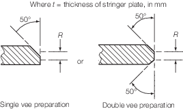
Table 10.2.5 Weld connection of strength deck
plating to sheerstrake
| Item
|
Stringer plate
thickness, mm
|
Weld type
|
| 1
|
t ≤ 15
|
Double continuous fillet weld with a
weld factor of 0,44
|
| 2
|
15 < t ≤ 20
|
Single vee preparation to provide included angle of 50° with
root R ≤ 1/3
t in conjunction with a continuous fillet weld having a weld
factor of 0,39
or
Double vee preparation to provide included angles of 50° with
root R ≤ 1/3
t
|
| 3
|
t > 20
|
Double vee preparation to provide
included angles of 50° with root R ≤ 1/3
t but not to exceed 10 mm
|
|
Note 1. Welding procedure, including joint preparation, is to be
specified. Procedure is to be qualified and approved for individual
Builders.
Note 3. For thickness t in excess of 20 mm the stringer
plate may be bevelled to achieve a reduced thickness at the weld
connection. The length of the bevel is in general to be based on a
taper not exceeding 1 in 3 and the reduced thickness is in general to
be not less than 0,65 times the thickness of stringer plate or 20 mm,
whichever is the greater.
Note 4. Alternative connections will be considered.
|
2.9 Slot welding
2.9.1 The slots are to have a minimum length of 75 mm and, in general, a
minimum width of twice the side plating thickness or 20 mm, whichever is the
greater. The ends of the slots are to be rounded. The space between the slots is not
to exceed 150 mm.
|