
Section
4 Pile design
4.1 Driven pile design
4.1.1 Generally speaking, the methodology for driven pile presented in ISO
19901-4 Petroleum and natural gas industries – Specific requirements for offshore
structures – Part 4: Geotechnical and foundation design considerations
presents a suitable basis for driven pile design.
4.1.2 Further guidance on driven pile design is given in the following Sections.
4.2 Pile axial capacity
4.2.1 It should be noted that the reliability of the ‘main text method’ for
axial capacity in sands in Section 8.1, ISO 19901-4 Petroleum and natural gas
industries – Specific requirements for offshore structures – Part 4:
Geotechnical and foundation design considerations is below that of the
CPT-based methods. Whilst the ‘main text method’ may be suitable for a preliminary
assessment of pile capacity, the CPT-based design methods, such as those presented
for sand in the Annex A of ISO 19901-4 Petroleum and natural gas industries –
Specific requirements for offshore structures – Part 4: Geotechnical and
foundation design considerations, generally present a more reliable method
for assessment of axial capacity. Lehane et al. (2017) make a comparison of
the different methods by examining the measured values of capacity to calculated
values and determination of the coefficient of variation of the different methods.
However, it should be noted that there are occasions when the CPT-based methods for
sand give a wide range of capacity estimates; therefore, it may be prudent to
calculate capacity using more than one method before committing to a design.
4.2.2 Aside from the main text method for clay in Section 8.1, ISO 19901-4
Petroleum and natural gas industries – Specific requirements for offshore
structures – Part 4: Geotechnical and foundation design considerations,
other methods for clays that may be applied include the Imperial College Pile Design
method, NGI-05 and Fugro-96 method, as referred to by Lehane et al.
(2017).
4.2.3 When selecting a method for design it is important to ensure that it is applicable
and calibrated to the soil types under question. For example, if the soil type is
unconventional, such as silt or carbonate, then it may be the case that a pile
capacity method cannot be directly applied, or that more than one method should be
considered for the same soil type to ensure that the range of possible soil and pile
behaviours is examined.
4.2.4 It is important that sufficient site investigation data is collected to allow a
confident application of a particular pile design method, both in terms of quantity
and quality.
4.2.5 For assessment of pile axial capacity, the use of a reliable pile design method is a
preferred approach, rather than an alternative that may place reliance upon proof of
pile capacity during installation. Use of dynamic testing during installation
requires significant experience in similar soil types and requires conversion to an
equivalent static capacity and application of various corrections (e.g. due to scour
or cyclic loading). This leads to uncertainty in pile length required and may create
longer piles with other impacts such as increased installation time and additional
noise, see for example Jardine et al. (2015).
4.2.6 Ageing of skin friction in sands and clays is a well-recognised concept. It may be
used but would require careful demonstration that it is valid for the soil
conditions and piles in question, taking into account various factors such as cyclic
loading, timing of maximum loads after installation and any pile brittleness effects
on the structure. It is important to differentiate between setup effects that occur
relatively quickly after driving is complete (i.e. days, weeks or months), versus
ageing effects that occur over a much longer time (i.e. months or years).
4.3 Pile lateral response
4.3.1 There are various PY curve models available for the analyses of lateral stiffness and
capacity in clays. The PY curve models tend to have an empirical, or semi empirical,
basis and were developed taking into account a range of different conditions –
either intentional, or coincidental. When selecting a PY curve model the following
conditions should be considered.
4.3.2 Cyclic or static loading: The load condition being analysed and whether it tends
towards cyclic or static when considering the soil types and their likely behaviour.
For example, for a 50 or 100 year in-place condition it is common to assume that
cyclic degradation has occurred and therefore a cyclic PY curve should be used.
However, under other conditions, such as fatigue loading, the majority of fatigue
damage may occur when the soil is not experiencing significant effects of cyclic
degradation (either due to lack of degradation or recovery from previous
degradation) and in this case it may be more appropriate to use static PY curves. A
final example is for pushover loading where the displacements involved are higher
than the zone typically affected by cyclic degradation and therefore at
displacements associated with ultimate pushover state, static resistance without
cyclic degradation is more appropriate (Gilbert et al., 2010).
4.3.3 Implementing the model as developed: Many PY curve models do not consider the effect
of axial loading on lateral response, or vice versa. In this case it is appropriate
to consider if the two loading types may interact and whether adjustment to the
model should be made to account for this. For example, the Jeanjean (2017)
model in clays would require axial loading to be accounted for.
4.3.4 It should be ensured that it is appropriate to apply the PY curve model to the soil
type(s) under question. For example, the pile tests used by Reese and Van Impe
(2005) to develop the PY curve model in stiff clay were performed in high
plasticity clay that shows a very large reduction in post peak resistance when
compared to more typical North Sea clays.
4.3.5 The concept of conservatism does not necessarily apply to the assessment
of lateral pile stiffness and capacity. For instance, it is not necessarily
conservative for a structure if the foundation model used is 'soft' or 'weak'.
Hence, the assessment of lateral pile capacity and stiffness should be as accurate
as possible, giving due attention to uncertainties where they exist.
4.4 PY curve models
4.4.1 Jeanjean (2017) presents a comprehensive discussion of the main
text PY curve model for clays as presented in ISO 19901-4 Petroleum and natural
gas industries – Specific requirements for offshore structures – Part 4:
Geotechnical and foundation design considerations and propose an updated
version that may be more appropriate. Through an examination of the theoretical
background the development of the method is explained and they further refine the
method and definition of input parameters and assumptions generally leading to a
significant increase in lateral resistance and stiffness for monotonic loading.
4.4.2 Zhang et al. (2017) further expand on the method for monotonic PY curves,
presented by Jeanjean (2017), to give a methodology for cyclic PY curves. The
method can account for non-symmetrical loading and a simplified approach can be
derived to allow easier integration of the PY curves into PSI modelling for
structural analyses. In order to use the simplified method, it would need
appropriate calibration for local soil conditions and the nature of cyclic loading
applicable to the structure in question.
4.4.3 The method proposed by Jeanjean (2017) and Zhang et al. (2017) requires
the input of site-specific direct simple shear strength test results for monotonic
and cyclic loading in order to derive the PY curve shape (i.e.
P/Pu with y/D). However, in cases where such data are
not available, for example in preliminary design, recommendations are given for
different shear strength ranges.
4.4.4 Jeanjean (2017) concludes that diameter effects are appropriately
captured within the method and as such the proposed method can be applied without
correction. The alpha value can be calculated using the main text method for axial
capacity in clays presented in ISO 19901-4 Petroleum and natural gas industries –
Specific requirements for offshore structures – Part 4: Geotechnical and
foundation design considerations. However, the final alpha value selected
for calculation of PY curves may also need adjustment to account for the combined
effect of axial and lateral loading.
4.5 Refined assessment of lateral pile response
4.5.1 It is generally recognised that the PY curve methods included in common
International Standards such as ISO 19901-4 Petroleum and natural gas Industries
– Specific requirements for offshore structures – Part 4: Geotechnical and
foundation design considerations are not appropriate for large diameter
piles except, perhaps, as a first approach to preliminary design. Byrne et al.
(2015) and Byrne (2017) present the results of the pile soil analyses
(PISA) project which aimed to provide a suitable process to design large diameter
piles as well as to provide a more accurate assessment for smaller diameter piles if
required. This process considered a rule-based method which takes basic strength and
stiffness parameters to derive soil reaction curves and a numerical based method
which takes more detailed strength and stiffness parameters combined with the use of
a suite of detailed three-dimensional finite element analyses to calibrate a simple
one-dimensional (1D) finite element model (i.e. PY curves). The rule-based method is
considered suitable for initial feasibility or concept designs, whereas the
numerical based method is generally considered necessary further into the detailed
design process.
4.5.2 As shown in Figure 3.4.1 Components of soil capacity considered under PISA methodology (reproduced
from Byrne, 2017), the PISA
methodology also considers additional sources of soil resistance to resist lateral
and moment loading including vertical stresses due to external wall friction, shear
force at the pile base and a base moment. These additional components of capacity
are usually combined with traditional PY curves used in a 1D finite element analyses
and in PSI models through the structural design process. However, caution should be
exercised with a more refined assessment to ensure that components of axial
resistance (e.g. friction) are not double counted as lateral resistance (or vice
versa) without an assessment of interaction to ensure the design does not become
unconservative.
4.5.3 Care should be taken with selection of soil properties given their
differing influence on ULS, SLS and FLS design cases and especially the influence of
cyclic loading on pile response and capacity. Byrne (2017) also recognises
that engineering judgement is required in using the process to ensure that factors
such as installation effects or cyclic loading are appropriately considered in use
of the methodology that has currently only been developed for static loading.
See
Ch 3, 4.4 PY curve models for further
discussion on PY curve methods.
4.6 Monopile design
4.6.1 A monopile design shall take into account the following aspects:
- all ULS, SLS and FLS requirements taking into account the load and
resistance factors where appropriate;
- it should be ensured that rotations and displacements (accumulated or
otherwise) do not exceed a specified limit over the required lifetime of the
monopile including pre-service, in-service and post service conditions. Any
rotations or displacements under applied loading may require to be added to
construction or installation tolerances during design; and
- generally speaking, an ULS design approach for lateral pile design is
unsuitable as excessive displacements would be required for full
mobilisation of lateral resistance. Therefore, a serviceability approach can
be taken for design. Determining appropriate monopile penetration depth may
be assisted by considering the decrease in pile head rotation with
increasing penetration. The required pile length may be indicated where any
benefits in terms of the performance of the pile (e.g. stiffness, rotation
or, perhaps, displacement) become very limited. According to Achmus et
al. (2017) this generally leads to a reliable design when combined
with an appropriate PY curve approach.
4.6.2 When designing monopiles it is important to take accumulated
displacements and rotations into account as they may impact the ability of the
foundation to function properly over the entire service life. Accumulated
displacements have been the subject of various research including Leblanc et al.
(2010) and Rudolph et al. (2014). In the current approaches, such as
those presented in ISO 19901-4 Petroleum and natural gas industries – Specific
requirements for offshore structures – Part 4: Geotechnical and foundation
design considerations, the direction of cyclic loading is assumed to be
constant, however, as presented by Rudolph et al. (2014), this is unlikely to
be the case with various short-term, seasonal and long-term variation in load
direction and magnitude. There are various relationships for predicting accumulated
rotation, including that in DGGT (2013) where a logarithmic approach is
suggested.
4.6.3 For monopiles it generally appears to be the case that variation in
loading direction causes displacements that may be significantly higher than that
caused by uni-directional loading. Therefore, it is important to assess the
potential accumulated displacement and rotation taking into account the soil type
and loading characteristics combined with appropriate methodology such as that
presented by Rudolph et al. (2014) and Leblanc et al. (2010). Where
accumulated rotations or displacements could be critical, it may be appropriate to
ensure that an appropriate safety margin is included either in the specified
allowable rotation or displacement or by application of load and material factors to
the design methods.
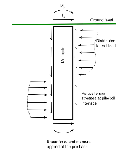
Figure 3.4.1 Components of soil capacity considered under PISA methodology (reproduced
from Byrne, 2017)
4.7 Driven pile axial capacity in chalk
4.7.1 Chalk is found extensively across north-west Europe and is a fine-grained material
consisting of calcite debris with a typical unconfined compressive strength (UCS) of
3–5 MPa and cone resistance in the order of 4–50 MPa (Carrington et al.,
2011).
4.7.2 According to Lord et al. (2002) axial shaft friction for driven open-ended
steel tubular piles should be limited to 20 kPa in low and medium density chalk and
shaft resistances in the order of 120 kPa may be expected in high-density grade A
chalk. Shaft resistance in chalk is dependent upon a number of mechanisms including
installation method, remoulding, excess pore pressures, ‘tightening’ of
discontinuities, strength of the chalk itself and the degree of porosity. Large
set-up may be expected after driving. For example, Buckley et al. (2017)
found that the remoulded zone varied in a range 0,59–1,64 times the pile wall
thickness.
4.7.3 The range of frictions presented by Lord et al. (2002) did not allow an
optimised design for low to medium density chalk and in recent years different
investigators have sought to improve the methodology.
4.7.4 Carrington et al. (2011) presented an assessment method for shaft resistance
based upon laboratory testing including cyclic direct simple shear tests and
presented an improvement for shaft friction such that a range of 20–50 kPa could be
used for low to medium density chalk. Ciavaglia et al. (2017) conducted a
series of onshore pile tests in low to medium density chalk and the results showed
that shaft friction a few days after driving was an average of 23 kPa and that, for
an aged pile, this increased sevenfold to 168 kPa. Buckley et al. (2017)
found similar results for driven piles where resistance at the end of driving was in
the range 15–17 kPa and a setup factor of up to 5,3 was found 246 days after
driving. Buckley et al. (2017) also tested the instrumented Imperial College
piles that were installed by pushing and they found that these piles had a setup
factor of less than 1,0: this has significant implications for some piles, such as
large diameter piles or those with significant structural weight applied during
installation, that are often installed to a greater or complete extent by
self-penetration and may not experience the same friction enhancing effects that
driven piles do.
4.7.5 When extrapolating the use of field tests into design, care should be taken to
include the effect of lateral loading on shaft friction. For example, Ciavaglia
et al. (2017) found that if a pile was subjected to lateral loads up to 50
per cent of the lateral capacity, the effect of setup was reduced such that shaft
resistance was up to 65 per cent lower. Efforts should therefore be made to assess
the degree to which lateral capacity will be mobilised and what influence this may
have on shaft friction and this will depend upon pile flexibility. In addition,
where using field tests to support offshore pile design it should be ensured that
the chalk characteristics and nature of the applied loading are similar; for
example, to take account of any cyclic effects. These effects will have different
impacts on monopiles or driven piles.
4.7.6 According to Lord et al. (2002) driving in grade A high density chalk can be
difficult, whereas driving in lower grade B, C and D chalk will be easier. Set-up
effects can be very significant and although this is beneficial for shaft resistance
it can have a significant impact if any driving delays are encountered, with a
higher risk of premature refusal.
4.8 Driven pile capacity in rock
4.8.1 High shaft frictions can be generated for driven piles in rock, for example, as
reported by Rodway and Rowe (1980) and Long (1991). The driven pile is
sometimes used with relief drilling to ensure that further pile penetration can be
achieved. As yet, there is little practical experience on shaft capacity in rock and
the impact of relief drilling on shaft capacity.
4.8.2 If driven piles in rock, with or without relief drilling, are critical to the pile
design (i.e. a significant proportion of the pile capacity is due to a driven
element in rock), then it may be prudent to perform appropriate pile testing to
optimise pile lengths. A non-optimal pile design may result in longer piles that
become too difficult to install with higher potential for premature refusal.
4.9 Drilled and grouted pile capacity
4.9.2 CIRIA (2004) gives a useful overview of issues of pile design in weak rock and
expansion of some key issues is provided in the following Sections.
4.9.3 Where it is expected that drilled and grouted piles may be used, then a literature
review should be performed to investigate methods that may be suitable for the
actual conditions and rock types likely to be encountered. The site investigation
and laboratory testing should then be designed such that sufficient information can
be gained for an efficient design. Key influencing factors of drilled & grouted
pile design include:
- cleanliness and roughness of the drilled hole which may be assessed during
site investigation and construction by the use of hole profiling techniques,
such as an acoustic televiewer;
- UCS of the rock using UCS tests. UCS test data may be supplemented by point
load test data provided the interpretation of results, for conversion to an
equivalent UCS strength, is properly calibrated;
- the site investigation should aim to identify the presence of
discontinuities or faults in the rock. Faults or discontinuities may cause
difficulty during installation either by hole collapse or by leakage of
grout;
- petrographic slices to investigate rock structure may help to understand the
likely response of the rock under loading. For example, it may be apparent
from a petrographic slice that the rock has an open structure that may be
vulnerable to collapse during installation or under applied stress;
- techniques such as P-S logging may provide an indication of overall response
of the rock mass; and
- CIRIA (2004) gives further discussion on parameters such as hole
roughness classification, adhesion factor and alpha value. Furthermore,
Williams and Pells (1981) describe the inclusion of a β factor to
account for the influence of rock quality on shaft friction.
4.9.4 In weak rock, an approach such as that by Kulhawy and Phoon (1993) may be
suitable for defining shaft resistance. It may be appropriate to apply a limit to
the frictions determined. Deliberate roughening may be used to enhance the shaft
friction; for example, by the inclusion of grooves in the drilled hole.
4.9.5 Once the shaft friction has been determined, it is necessary to confirm
that grout-steel friction will not limit the amount of shaft friction that can be
mobilised. The methodology presented in ISO 19902 Petroleum and natural gas
industries – Fixed steel offshore structures for calculating the capacity of
a grouted connection may be used; making appropriate assumptions for the smoothness
of the pile steel surface.
4.9.6 If excessive debris has collected near to the hole base and remains present then end
bearing may only be mobilised at excessive displacements; unless the debris is
removed. Furthermore, unless the pile is plugged (e.g. by grout) the end bearing
will be restricted to that on the pile annulus although this may be substantial. It
should also be noted that the displacements required to mobilise end bearing may be
such that significant degradation is caused on shaft friction and in this case it is
common practice to only count shaft friction or end bearing in design.
4.9.7 It may also be appropriate to consider the use of pile testing in similar rock types
(perhaps onshore) to optimise the pile design or laboratory tests, such as constant
normal stiffness interface friction testing, to help definition of pile
behaviour.
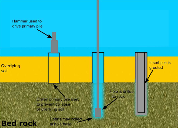
Figure 3.4.2 Typical drilled and grouted pile configuration
4.9.8 There are a number of potential issues to be considered during installation of
drilled and grouted piles. These include:
- during drilling, it should be ensured that the hole will remain
open sufficiently long in order that the pile can be installed and the
grouting operation completed. If the hole does not remain stable, then it is
possible that the pile capacity will be degraded and collapse of soil or
rock around the hole may occur. This collapse of soil could undermine any
mudmats that are being used to provide temporary stability. Hole stability
issues can be overcome by using a driven primary pile until stable rock or
soil conditions are reached; then an insert pile will be used to form the
grouted section;
- if using blind-ended (or closed-ended) tubular piles it should be checked
that the pile will not float once grout has been placed and prior to
setting; and
- where drilling fluids other than seawater are used their impact on the pile
performance should be assessed.
4.10 Suction caisson design
4.10.1 Where suction caissons (also called suction piles or suction buckets) are
considered, it should be first established that the concept is applicable.
4.10.2 In addition to general aspects discussed under the design basis, the design process
will need to make assumptions around the following aspects that will then be further
refined through the design process:
- cyclic effects;
- conditions or assumptions conditions such as contact of the caisson lid with
soil, or under lid grouting where appropriate;
- whether suction assistance is required during installation; or if the
caissons will penetrate under self-weight of the structure and foundation;
- the combination of suction caisson penetration and the necessity of an
allowance for heave of the internal soil plug during installation; and
- installation and extraction may be more sensitive to soil type and soil
layering than may generally be expected for alternative foundation types
such as driven piles.
4.10.3 It is common to practise perform sizing of a suction caisson using
simplified methodology such as the work by Suryasentana et al. (2017) or
alternative formulations of upper bound methods, see for example Hamilton and
Murff (1995). Following this the suitability of design should then be
confirmed suitable by the use of finite element analyses that can more precisely
take into account aspects such as soil layering or other soil properties.
4.10.4 Where a structural analysis requires stiffness input it should be ensured that the
stiffness matrix in the structural analyses is compatible with the level of loads
used. Many structural analyses packages only accept a linear stiffness matrix input
and in this case it may be necessary to iterate the stiffness matrix until
compatibility between loads and stiffness is achieved. It may be necessary to vary
the stiffness matrix depending on what is critical to the analyses and associated
load levels. For example, the load levels and impact of cyclic degradation may be
quite different for ULS loading (where fewer bigger waves occur) when compared to
FLS loading.
4.10.5 An initial estimate of suction pile stiffness may be made using the methodology
published by Suryasentana et al. (2017) or Doherty et al. (2005) and
validated by finite element analyses as appropriate.
4.10.6 Detailed design will also require an estimate of the long-term performance of the
foundation to ensure that rotations and displacements remain within acceptable
limits. This aspect was investigated by Zhu et al. (2017) for response of
suction caissons in single-layer and layered seabeds and an expression for
accumulated rotation is provided along with the required calibration parameters
depending on soil conditions and relative layer thicknesses. The current work has
focussed on uni-directional loading and further development or validation is
required before applying the methodology to multi-directional loading.
4.10.7 An installation assessment can be performed using methodology such as that by
Andersen et al. (2008), Senders and Randolph (2009) or Houlsby and Byrne (2005). Key
considerations include:
- determining if suction assisted installation is required (i.e. suction
installed); or whether the caissons will penetrate under the combination of
their own weight and the structure (i.e. may be considered as jacked);
- estimating heave of the soil plug during installation;
- potential for cavitation of water during suction installation; and
- potential mitigation measures and their impact on the foundation should
early refusal be experienced. Such measures may include the use of ballast,
cycling of suction pressure or water injection.
4.10.8 If re-spudding of the caisson is required, due to refusal or some other installation
issue, the required offset distance from the refusal location should be considered
such that there is no significant impact upon the installed foundation.
4.10.9 Where experience in local or comparable soil or seabed conditions is not available,
then it may be prudent to perform field trials of suction caisson installation
before committing to the concept.
|