5.2.1 It is important to note that in nitrided crankshaft cases, fatigue is
found either at the surface or at the transition to the core. This means that the
fatigue strength can be determined by tests as described in Ch 2 Guidance for Evaluation of Fatigue Tests.
5.2.2 Alternatively, the surface fatigue strength (principal stress) can be
determined empirically and conservatively as:
This is valid for a surface hardness of 600HV or greater:
Note that this fatigue strength is assumed to include the influence of the surface
residual stress and applies for a working stress ratio of R = -1.
5.2.3 The fatigue strength in the transition-zone can be determined by the
equation introduced in the ‘Fatigue strength’ sub-section of the applicable Rules.
For crankpin and respectively to journal the following applies:
|
|
where
|
|
|
|
Y = DG
|
and
|
X = RG
|
|
for journal fillet
|
|
|
|
Y = D
|
and
|
X = RH
|
|
for crankpin fillet
|
|
|
|
Y = D
|
and
|
X =
DO/2
|
|
for oil bore outlet
|
Note that this fatigue strength is not assumed to include the influence of the
residual stresses.
5.2.4 In contrast to induction-hardening, the nitrided components have no such
distinct transition to the core. Although the compressive residual stresses at the
surface are high, the balancing tensile stresses in the core are moderate because of
the shallow depth. For the purpose of analysis of subsurface fatigue, the
disadvantage of tensile residual stresses in and below the transition zone may even
be disregarded in view of this smooth contour of a nitriding hardness profile.
5.2.5 Although in principle the calculation should be carried out along the
entire hardness profile, it can be limited to a simplified approach of examining the
surface and an artificial transition point. This artificial transition point can be
taken at the depth where the local hardness is approximately 20 HV above the core
hardness. In such a case, the properties of the core material should be used. This
means that the stresses at the transition to the core can be found by using the
local SCF formulae in Ch 3, 5.1 Nitriding general comments 5.1.3,
inserting t=1,2tN.
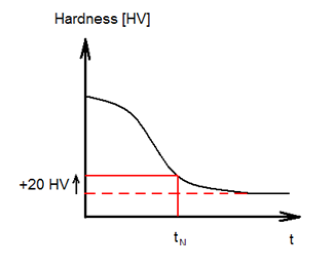
Figure 3.5.1 Sketch of the location for the artificial transition point in the depth
direction