
Section
3 Structural Design
3.1 General
3.1.1 Mitre gates and flap gates are to be considered as single plates with
vertical girders and horizontal stringers attached. Other configurations will be
specially considered.
3.1.2 For floating dock gates where the principal dimensions B and
D are such that the breadth B is the same as the span of the deck
beams (i.e. no intermediate support is provided) and the depth D is less than
6 metres, then the side shell and transverse bulkheads can be considered as a double
plate bulkhead.
3.1.3 Sufficient support is to be provided such as ensures 100 per cent end
fixity for all members.
3.2 Welding and structural details
3.3 Structural idealisation
3.3.1 For derivation of scantlings of stiffeners, beams, girders, etc. the formulae in the
Rules are normally based on elastic or plastic theory using simple beam models
supported at one or more points associated with an appropriate concentrated or
distributed load.
3.3.2 Apart from local requirements for web thickness or flange thicknesses, the stiffener,
beam or girder strength is defined by a section modulus and moment of inertia
requirement.
3.3.3 The effective geometric properties of rolled or built sections can be calculated
directly from the dimensions of the section and associated effective area of
attached plating. Where the web of the section is not normal to the attached
plating, and the angle exceeds 20°, the properties of the section are to be
determined about an axis parallel to the attached plating.
3.3.4 The geometric properties of rolled or built stiffener sections are to be calculated
in association with effective area of attached load bearing plating of thickness
tp mm and of width 600 mm or 40 tp mm,
whichever is the greater. In no case, however, is the width of plating to be taken
as greater than the spacing of the stiffeners. The thickness, tp,
is the actual thickness of the attached plating. Where this varies, the mean
thickness over the appropriate span is to be used.
3.3.5 The effective section modulus of a built section can be taken as:
where
|
a |
= |
the area of the face plate of the member, in cm2 |
|
dw |
= |
the depth, in mm, of the web between the inside of the face plate and
the attached plating. |
|
tw |
= |
the thickness of the web of the section, in mm |
|
A |
= |
the area, in cm2, of the attached plating,
see
Pt 2, Ch 2, 3.3 Structural idealisation 3.3.6.
If the calculated value of A is less than the face area a,
then A is to be taken as equal to a. |
3.3.6 The geometric properties of primary support members (i.e. girders,
transverses, webs, stringers, etc.) are to be calculated in association with an
effective area of attached load bearing plating, A, determined as
follows:
where
|
f |
= |
 , but is not to exceed 1,0. Values of
this factor are given in Table 2.3.1 Load bearing plating
factor , but is not to exceed 1,0. Values of
this factor are given in Table 2.3.1 Load bearing plating
factor |
|
b |
= |
the actual width, in metres, of the load-bearing plating,
i.e. one-half of the sum of spacings between parallel adjacent members
or equivalent supports |
|
l |
= |
the overall length, in metres, of the primary support
member, see
Figure 2.3.2 Span points |
|
tp |
= |
the thickness, in mm, of the attached plating. Where this
varies, the mean thickness over the appropriate span is to be used. |
3.3.7 The effective length, le, of a stiffening member is generally less
than the overall length, l, by an amount which depends on the design of the
end connections. The span points, between which the value of le is
measured, are to be determined as follows:
- For rolled or built secondary stiffening members:
The span point is to be taken at the point where the depth
of the end bracket, measured from the face of the secondary stiffening
member, is equal to the depth of the member. Where there is no end
bracket, the span point is to be measured between primary member webs.
For double skin construction, the span may be reduced by the depth of
the primary member web stiffener, see
Figure 2.3.2 Span points.
- For primary support members:
The span
point is to be taken at a point distant from the end of the member,
where
See also
Figure 2.3.2 Span points.
3.3.8 Where the stiffener member is inclined to a vertical or horizontal axis and the
inclination exceeds 10°, the span is to be measured along the member.
3.3.9 Where it is assumed that the side shell and transverse bulkheads of a
floating dock gate are acting as a double plate bulkhead, the effective section
modulus of the combined section is to be calculated as follows:
where
|
dw |
= |
the breadth of the dock gate, B, in metres |
|
dt |
= |
the bulkhead plate thickness, in mm |
|
tp |
= |
the side shell plate thickness, in mm |
|
b |
= |
one-half of the sum of the spacings between adjacent
transverse bulkheads (including the ends of the floating dock gate) |
f is defined in Pt 2, Ch 2, 3.3 Structural idealisation 3.3.6
where l is taken as the depth D of the floating dock gate
See also
Figure 2.3.1 Double plate bulkhead
dimensions.
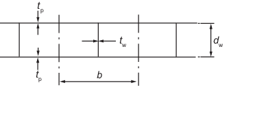
Figure 2.3.1 Double plate bulkhead
dimensions
Table 2.3.1 Load bearing plating
factor

|
f
|

|
f
|
| 0,5
|
0,19
|
3,5
|
0,69
|
| 1,0
|
0,30
|
4,0
|
0,76
|
| 1,5
|
0,39
|
4,5
|
0,82
|
| 2,0
|
0,48
|
5,0
|
0,88
|
| 2,5
|
0,55
|
5,5
|
0,94
|
| 3,0
|
0,62
|
6,0 and above
|
1,00
|
|
Note Intermediate values are to be obtained by linear
interpolation
|
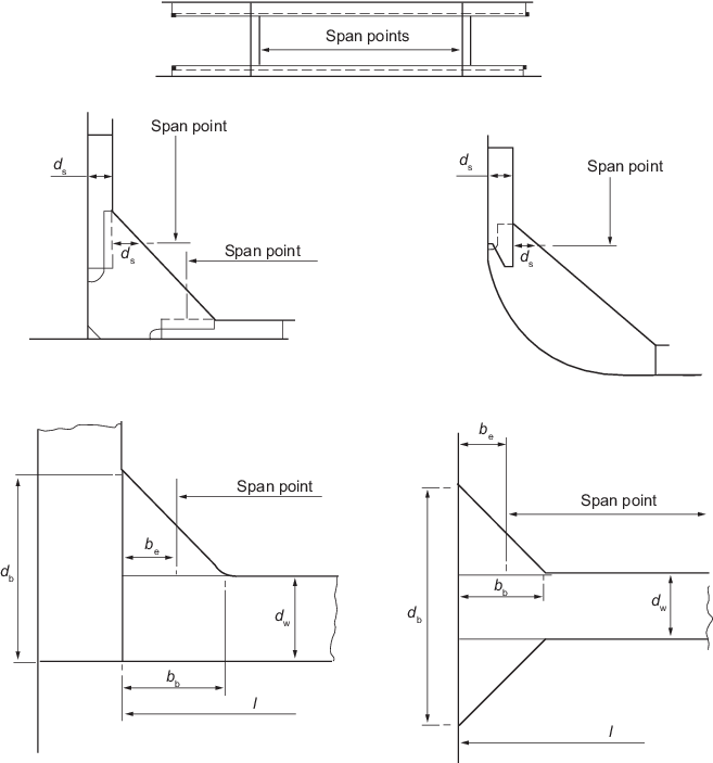
Figure 2.3.2 Span points
|