4.2.2 The applied load should be verified by strain gauge measurements on plain
shaft sections. It is also pertinent to check fillet stresses with strain gauge
chains.
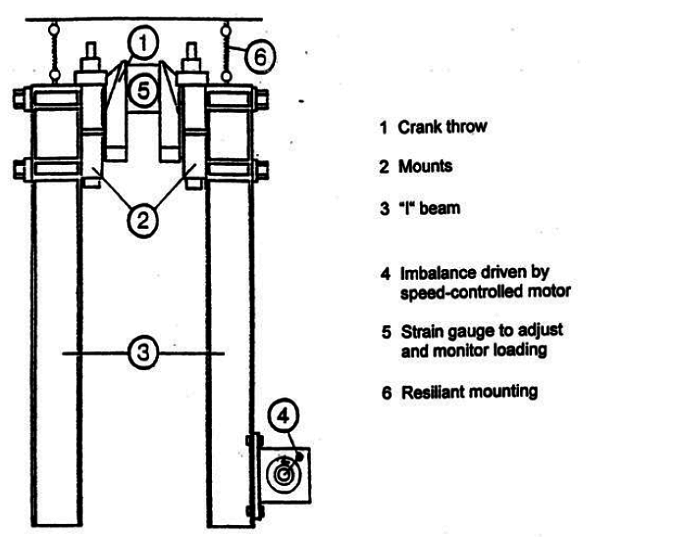
Figure 2.4.1 An example of testing arrangement of the resonance tester for bending
loading
4.2.3 Clamping around the journals must be arranged in a way that prevents severe fretting
which could lead to a failure under the edges of the clamps. If some distance
between the clamps and the journal fillets is provided, the loading is consistent
with 4-point bending and thus also representative for the journal fillets.
4.2.4 In an engine, the crankpin fillets normally operate with an R-ratio slightly
above -1 and the journal fillets slightly below -1. If found necessary, it is
possible to introduce a mean load (deviate from R = -1) by means of a spring
preload.
4.2.6 This sideways movement of the clamped-on weights can be reduced by having
two crank throws, especially if the cranks are almost in the same direction.
However, the journal in the middle will move more.
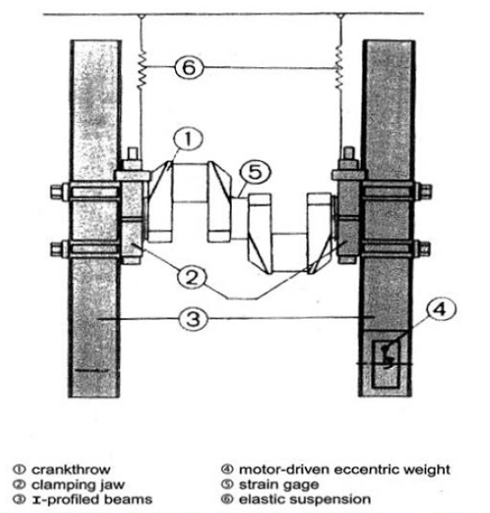
Figure 2.4.2 An example of testing arrangement of the resonance tester for torsion
loading with double crank throw section
4.2.7 Since sideway movements can cause some bending stresses, the plain portions of the
crankpins should also be provided with strain gauges arranged to measure any
possible bending that could have an influence on the test results.
4.2.8 Similarly to the bending case, the applied load shall be verified by strain gauge
measurements on plain shaft sections. It is also pertinent to check fillet stresses
with strain gauge chains as well.