
Section
2 Towing
2.1 Application
2.1.1 The strength of shipboard fittings used for normal towing operations at bow, sides
and stern and their supporting hull structures are to comply with the requirements
specified in this sub-Section.
2.2 Arrangements
2.2.1 Shipboard fittings for towing are to be located on stiffeners and/or girders which
are part of the deck construction so as to facilitate efficient distribution of the
towing load. Other arrangements are acceptable, provided that the strength is
confirmed adequate for the intended service.
2.3 Design load
2.3.1 The design load applied to shipboard fittings and supporting hull structure is not to
be less than 1,25 times the intended maximum towing load (e.g. static bollard pull)
as indicated on the towing arrangements plan.
2.3.2 When a safe towing load (TOW) greater than that determined according to
Pt 3, Ch 10, 2.8 Safe towing load (TOW) 2.8.1 is
requested, then the design load is to be increased in accordance with the
appropriate TOW/design load relationship given in this Section.
2.3.3 The side projected area is to be considered for selection of towing lines and the
loads applied to shipboard fittings and supporting hull structure.
2.3.4 The increase of the minimum breaking strength for synthetic ropes need not to be
considered for the loads applied to shipboard fittings and supporting hull
structure.
2.3.5 The design load is to be applied to fittings in all directions that could
occur by considering the arrangement shown on the towing and mooring arrangements
plan. Where the towing line takes a turn at a fitting, the total design load applied
to the fitting is equal to the resultant of the design loads acting on the line,
see
Figure 10.2.1 Design load applied to
fittings.
However, in no case does the design load applied to the fitting need to be greater
than twice the design load on the line.
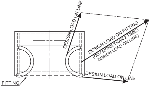
Figure 10.2.1 Design load applied to
fittings
2.4 Strength of fittings
2.4.1 Shipboard fittings are to be selected from an acceptable National or International
Standard and to be based on the intended maximum towing load (e.g. static bollard
pull) as indicated on the towing arrangements plan.
2.4.2 Towing bitts (double bollards) are to be chosen for the towing line attached with an
eye splice if the industry standard distinguishes between different methods to
attach the line, i.e. figure-of-eight or eye splice attachment.
2.4.3 When the shipboard fitting is not selected from an accepted industry
standard, the strength of the fitting based on net scantlings and its attachment to
the ship is to be adequate for the loads specified in Pt 3, Ch 10, 2.3 Design load 2.3.1 based on the
acceptance criteria given in Pt 3, Ch 10, 2.5 Strength of supporting hull structures 2.5.2 or Pt 3, Ch 10, 2.5 Strength of supporting hull structures 2.5.3 as appropriate. Towing bitts (double bollards) are required
to resist the loads caused by the towing line attached with an eye splice. For
strength assessment, beam theory or finite element analysis using net scantlings is
to be applied, as appropriate. Corrosion additions and wear down allowance is to be
added to the net scantlings as defined in Pt 3, Ch 10, 2.6 Corrosion addition and Pt 3, Ch 10, 2.7 Wear allowance.
2.5 Strength of supporting hull structures
2.5.1 The net scantlings of the supporting hull structure for the fittings are
to be adequate for the loads specified by the Pt 3, Ch 10, 2.3 Design load 2.3.1
based on the acceptance criteria given in by Pt 3, Ch 10, 2.5 Strength of supporting hull structures 2.5.2 or Pt 3, Ch 10, 2.5 Strength of supporting hull structures 2.5.3 as appropriate. The reinforced members beneath
shipboard fittings are to be effectively arranged for any variation of direction
(horizontally and vertically) of the towing forces acting upon the shipboard
fittings, see
Figure 10.2.2 Supporting hull structure for a sample arrangement. Proper alignment of the
fitting and its supporting hull structure is to be ensured. The acting point of the
towing force on a shipboard fitting is to be taken at the attachment point of a
towing line or at a change in its direction. For bollards and bitts the attachment
point of the towing line is to be taken not less than 4/5 of the tube height above
the base as indicated in Figure 10.2.2 Supporting hull structure Corrosion additions and wear down allowance are to be added to
the net scantlings as defined in Pt 3, Ch 10, 2.6 Corrosion addition and
Pt 3, Ch 10, 2.7 Wear allowance.
2.5.3 For strength calculations by means of finite element analysis, the geometry is to be
idealised as realistically as possible. The ratio of element length to width is not
to exceed 3. Girders are to be modelled using shell or plane stress elements.
Symmetric girder flanges are generally to be modelled by beam or truss elements. At
least three elements are to be used across the depth of the girder. In way of small
openings in girder webs the web thickness is to be reduced to a mean thickness over
the web height. Large openings are to be modelled. Stiffeners are generally to be
modelled by using shell, plane stress, or beam elements. Stresses are to be read
from the centre of the individual element. For shell elements the stresses are to be
evaluated at the mid- plane of the element. The equivalent stress within the
supporting structure of fittings is not to exceed the specified minimum yield
strength of the material.
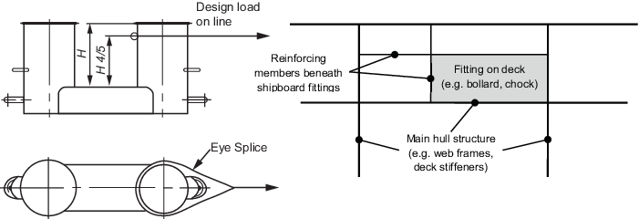
Figure 10.2.2 Supporting hull structure
Table 10.2.1 Allowable stress within the supporting structure of shipboard
fittings
|
|
Normal stress, in N/mm2
|
Shear stress, in N/mm2
|
| Allowable stress
|

|

|
| where
σo = specified minimum yield
strength of the material in N/mm2
Note Normal
stress is defined as the sum of bending and axial stresses. No
stress concentration factors are accounted for and as such may
need to be considered separately.
|
2.6 Corrosion addition
2.6.1 An allowance for corrosion is to be added to the net thickness derived as indicated
below:
- For the supporting hull structure, a corrosion addition of 2
mm is to be added to the net thickness derived.
- For pedestals and foundations on deck which are not part of
a fitting according to an accepted industry standard, 2,0 mm.
- For shipboard fittings not selected from an accepted
industry standard, 2,0 mm.
2.7 Wear allowance
2.7.1 In addition to the corrosion addition given in Pt 3, Ch 10, 2.6 Corrosion addition, the wear
allowance, tw, for shipboard fittings that are not selected from
an acceptable National or International standard, is not to be less than 1,0 mm,
added to surfaces which are intended to regularly contact the line.
2.8 Safe towing load (TOW)
2.8.1 The safe towing load (TOW) is the load limit for towing purposes. The TOW
used is not to exceed 80 per cent of the design load specified by Pt 3, Ch 10, 2.3 Design load 2.3.1.
2.8.2 The TOW, in tonnes, of each shipboard fitting is to be marked (by weld bead or
equivalent) on the deck fittings used for towing.
2.8.3 The above requirements on the TOW apply for the use with no more than one towline
line. If not otherwise chosen, for towing bitts (double bollards) the TOW is the
load limit for a towing line attached with an eye-splice.
|
| Copyright 2022 Clasifications Register Group Limited, International Maritime Organization, International Labour Organization or Maritime
and Coastguard Agency. All rights reserved. Clasifications Register Group Limited, its affiliates and subsidiaries and their respective
officers, employees or agents are, individually and collectively, referred to in this clause as 'Clasifications Register'. Clasifications
Register assumes no responsibility and shall not be liable to any person for any loss, damage or expense caused by reliance
on the information or advice in this document or howsoever provided, unless that person has signed a contract with the relevant
Clasifications Register entity for the provision of this information or advice and in that case any responsibility or liability is
exclusively on the terms and conditions set out in that contract.
|
 |
|