
Section
7 Corrosion additions
7.1 General
7.2 Net scantling approach
7.2.1 The net thickness of a structural element is that required for structural
strength compliance with the design basis. The corrosion addition for structural
elements is derived independently of the net scantling requirements. This approach
clearly separates the net thickness from the thickness added to address the
corrosion that is likely to occur during the in-operation phase. This approach
enables the status of the structure with respect to corrosion to be clearly
ascertained throughout the life of the unit. See
Figure 3.7.1 Example calculations of
corrosion additions.
7.2.2 The net thickness approach distinguishes between local and global
corrosion. Local corrosion is defined as uniform corrosion of local structural
elements, such as a single plate or stiffener. Global corrosion is defined as the
overall average corrosion of larger areas such as primary support members and the
hull girder.
7.3 Corrosion additions
7.3.1 The corrosion additions specified in this sub-Section are applicable to
each of the two sides of a structural member and are given as a corrosion rate. The
corrosion rate for each of the two sides of a structural member is specified in
Table 3.7.1 Corrosion rate for one side of
structural member. However, consideration
will be given to alternative corrosion rates if these are contractually agreed
between the Owner and Shipyard.
7.3.3 The corrosion rates for cargo and ballast water tanks given in Table 3.7.1 Corrosion rate for one side of
structural member assume the tanks will
spend 50 per cent of the time empty and 50 per cent of the time full over the unit
design life and that the ballast tank is fitted with effective anodes. Where
alternative regimes for individual tanks are specified, the corrosion rate may be
adjusted by [percentage time empty/50] x corrosion rate from Pt 4, Ch 3, 7.4 Scantling compliance 7.4.6. The percentage time empty is not to be
taken as less than 25 per cent.
7.3.4 The default coating life is to be taken as 15 years. Alternative
corrosion additions may be derived using the general principles shown in Figure 3.7.2 Generic example unit life
cycle where an alternative coating
life is specified.
7.3.5 To address the risk of pitting corrosion, the gross thickness of the
bottom plating of tanks is not to be less than:
|
tgrs |
= |
6 + Nt (20tc1+
tc2) |
where
|
Nt |
= |
number of years between surveys (not to be taken as less than 5
for new builds or 2,5 for conversions) |
tc1 and tc2 are defined in Pt 4, Ch 3, 7.3 Corrosion additions 7.3.2. tc1 is the value for the
side of the structural member within the tank.
- Explanatory note:
- This requirement ensures that there is sufficient bottom
plating thickness remaining at thickness measurement survey so that pitting
corrosion should not lead to loss of barrier integrity between
inspections.
7.4 Scantling compliance
7.4.2 The net section modulus, moment of inertia and shear area properties of
local support members are to be calculated using the net thicknesses of the attached
plate, web and flange.
7.4.3 The net section properties, shear area and section modulus of primary
support members are to be calculated using the net thicknesses of the attached
plate, web and flange plus half of the applicable corrosion addition specified in
Pt 4, Ch 3, 7.3 Corrosion additions.
7.4.4 The net scantlings described in this sub-Section are related to gross
scantlings as follows:
- for application of the minimum thickness requirements, the gross
thickness is obtained from the applicable requirements by adding the full
corrosion additions specified in Pt 4, Ch 3, 7.3 Corrosion additions;
- for plating and local support members, the gross thickness and
gross cross-sectional properties are obtained from the applicable
requirements by adding the full corrosion additions specified in Pt 4, Ch 3, 7.3 Corrosion additions;
- for primary support members, the gross shear area, gross
section modulus and other gross cross-sectional properties are obtained from
the applicable requirements by adding one half of the relevant full
corrosion additions specified in Pt 4, Ch 3, 7.3 Corrosion additions;
- for application of buckling requirements, the gross thickness
and gross cross-sectional properties are obtained from the applicable
requirements by adding the full corrosion additions specified in Pt 4, Ch 3, 7.3 Corrosion additions.
7.4.5 Any additional thickness specified by the Owner as Owner’s extra margin
is not to be included when considering compliance with this Section.
7.4.6 The corrosion allowance to be deducted from the gross scantlings prior
to the compliance assessment is given in Table 3.7.2 Corrosion allowance to be
deducted from the gross scantlings prior to the compliance assessment.
Table 3.7.1 Corrosion rate for one side of
structural member
| Compartment type
|
Structural member
|
Corrosion rate tc1,
tc2(mm/year)
|
| Ballast water and
preload tanks (see Note 6)
|
within 3m below top of tank,
see Note 1
|
0,15
|
| Elsewhere
|
0,1
|
| Cargo oil tank
(see Note 3)
|
within 3m below top of tank,
see Note 1
|
0,125
|
| Bottom of tanks
|
0,125
|
| Elsewhere
|
0,075
|
| Exposed to
atmosphere
|
Weather deck plating
|
0,1
|
| Other members
|
0,075
|
| Exposed to sea
water (see Notes 6 and 7)
|
Shell plating
|
0,075
|
| Legs of self-elevating
units
|
0,075
|
| Exposed to sea bed and
seawater
|
Legs, footings, mats of
self-elevating units
|
0,2 (see Note 8)
|
| Fuel
and lubricating oil tank see (see Note 4)
|
0,05
|
| Fresh
water tank
|
0,05
|
| Slop
tanks
|
0,15
|
| Void spaces, see Note
2
|
Spaces not normally accessed,
e.g. access only via bolted manhole openings, pipe tunnels, inner
surface of stool space common with a dry bulk cargo hold,
etc.
|
0,05
|
| Dry spaces
|
Internals of machinery spaces,
pump room, store rooms, steering gear space, etc
|
0,05
|
| Hold space bounding membrane
liquefied gas tanks
|
side of hull structure within
hold space where there is environmental control such as
inerting
|
0
|
|
Note 1 This is only
applicable to cargo tanks and ballast tanks with weather deck as
the tank top.
|
|
Note 2. The
corrosion rate on the outer shell plating in way of a pipe
tunnel is to be taken as for a water ballast tank.
|
|
Note 3. 0,05 mm/year
is to be added to the plate surface exposed to ballast for the
plate boundary between water ballast and heated cargo oil tanks.
0,03 mm/year is to be added to each surface of the web and face
plate of a stiffener in a ballast tank and attached to the
boundary between water ballast and heated cargo oil tanks.
Heated cargo oil tanks are defined as tanks arranged with any
form of heating capability.
|
|
Note 4. 0,07 mm/year is to be added to the plate surface exposed to
ballast for the plate boundary between water ballast and heated
fuel oil tanks or lube oil tanks.
|
|
|
|
Note 6. The
corrosion rates indicated assume effective anodes are fitted to
the steel boundary.
|
|
Note 7. Additional
corrosion allowance in the splash zone is recommended.
|
|
Note 8. Additional
margins greater than those indicated in the table may be
required where the members are subject to high corrosion/wear
rates.
|
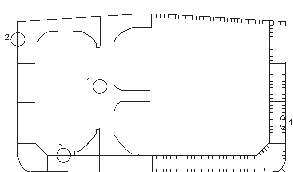
1 Longitudinal bulkhead plating
2 Side shell plating (within 3 m below top of tank
3 Cargo tank bottom plating
4 Stiffeners in ballast water tank
Note This example assumes that the
tanks will spent 50 per cent of the time empty and 50 per cent of the time full
over the unit design life.
Figure 3.7.1 Example calculations of
corrosion additions
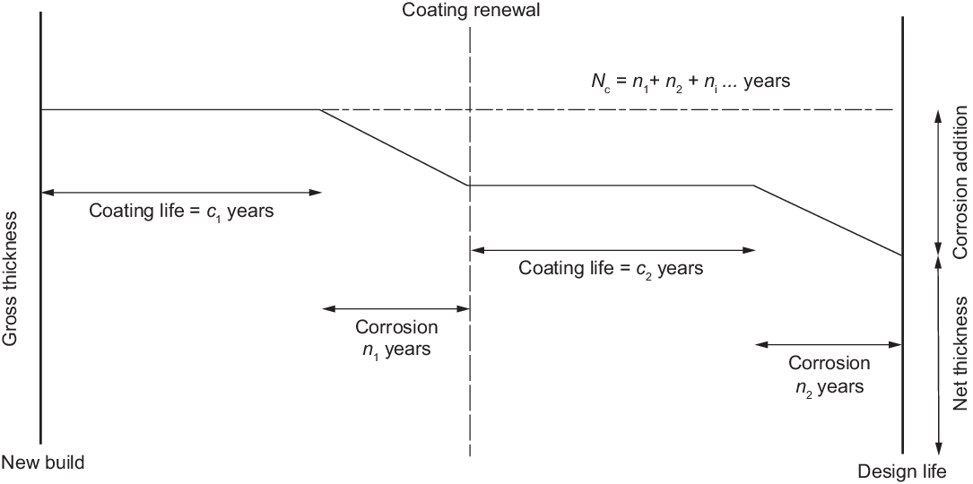
Figure 3.7.2 Generic example unit life
cycle
Table 3.7.2 Corrosion allowance to be
deducted from the gross scantlings prior to the compliance assessment
| Assessment
|
Stress
calculations
|
Buckling capacity calculations
|
| Minimum
thickness
|
Thickness
|

|
N/A
|
| Local strength (plates, stiffeners, and hold frames)
|
Thickness/sectional properties
|

|
N/A
|
| Stiffness/proportions
|

|

|
| Primary
support members
|
Thickness/sectional properties
|
0,5
|
N/A
|
| (Prescriptive)
|
Stiffness/proportions of web and flange
|

|

|
| Strength
|
Global coarse
mesh
|
0,5
|

|
| Local fine
mesh
|

|
| Fatigue
|
Global coarse
mesh
|
0,25
|
N/A
|
| Local fine
mesh
|
0,5
|
| Sloshing
|
Sloshing
|

|

|
| Fracture
|
Global coarse
mesh
|
0,25
|
N/A
|
| Local extremely
fine mesh
|
0,5
|
| Ultimate
strength
|
Ultimate
strength
|
0,5
|
0,5
|
|
Note For the
assessment, the gross scantling used is not to include any
Owner’s extra.
|
|