
1 Tank barge example
1.1 General
-
1.1.1 The application of the Accidental Oil Outflow
Performance regulation is shown in the following worked example illustrating
the calculation procedure for a tank barge.
-
1.1.2 The arrangement and dimensions of the sample
barge are as shown figure 26.
For clarity purposes, a simple arrangement has been selected which
does not comply with all MARPOL requirements. However, for actual
designs, the vessel must satisfy all applicable regulations of MARPOL Annex I.
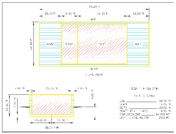
Barge Arrangement
1.2 Establishing the nominal cargo oil density
-
1.2.1 The deadweight (DW) equals the displacement
at the summer load line draft measured in seawater with a density
of 1.025 t/m3 minus the lightship. No deduction is taken
for consumables.
-
1.2.2 The cargo volume C equals the total cargo
volume at 98% filling. In accordance with paragraph 4.5 of regulation 23, the capacity of
cargo tanks are calculated based on a permeability of 0.99.
|
|
100%
Capacity
(m3)
|
98%
Filling
(m3)
|
| CO1
|
9,623
|
9,430
|
| CO2
|
28,868
|
28,291
|
|
|
C=
|
37,721
|
-
1.2.3 In accordance with paragraph 4.4 of regulation 23, the nominal density
is calculated as follows:
1.3 Calculating the probabilities of side damage
-
1.3.1 The first step is to determine the values
for the dimensions and clearances Xa, Xf, Zl ,
Zu and y as defined in paragraph 8.2 of regulation 23:
| Tank
|
Xa
m-AP
|
Xf
m-AP
|
Zl
m-BL
|
Zu
m-BL
|
y
m
|
| CO1
|
20.000
|
35.000
|
2.000
|
20.000
|
2.000
|
| CO2
|
35.000
|
80.000
|
2.000
|
20.000
|
2.000
|
|
|
|
|
|
|
|
-
1.3.2 From the ratios Xa/L, Xf/L,
Z/Bs, Zl/Ds, Zu/Ds,
Yl/Ds, and y, the probabilities associated with
these subdivision locations are interpolated from the table of probabilities
for side damage provided in Paragraph 8.3 of regulation 23. For instance, for
compartment CO1, the forward boundary Xf is at 35.0 m from
the A.P, and Xf/L = 0.35. From the table, we find that
Psf = 0.617. The probabilities for CO1 and CO2 are as follows:
| Tank
|
Xa/L
|
PSa
|
Xf/L
|
PSf
|
Zl/DS
|
PSl
|
Zu/DS
|
Psu
|
y/Bs
|
Psy
|
| CO1
|
0.2000
|
0.1670
|
0.3500
|
0.6170
|
0.1000
|
0.0010
|
0.1000
|
0.0000
|
0.0500
|
0.7490
|
| CO2
|
0.3500
|
0.3170
|
0.8000
|
0.1670
|
0.1000
|
0.0010
|
0.1000
|
0.0000
|
0.0500
|
0.7490
|
|
|
|
|
|
|
|
|
|
|
|
|
-
1.3.3 In accordance with paragraph 8 of regulation 23, the probability
factors are then combined to find the probability, Ps,
of breaching a compartment from side damage.
-
For tank CO1:
PSL = (1 - Psf -
Psa) = (1 - 0.617 - 0.167) = 0.216
PSV = (1 - Psu - Psl) = (1
- 0.000 - 0.001) = 0.999
PST = (1 - Psy) = (1 - 0.749) = 0.251
Ps = PSL PSV PST =
(0.216)(0.999)(0.251) = 0.0542
-
For tank CO2:
PSL = (1 - Psf -
Psa) = (1 - 0.167 - 0.317) = 0.516
PSV = (1 - Psu - Psl) = (1
- 0.000 - 0.001) = 0.999
PST = (1 - Psy) = (1 - 0.749) = 0.251
Ps = PSL PSV PST =
(0.216)(0.999)(0.251) = 0.1294
-
1.3.4 Given a collision that penetrates the outer
hull, Ps is the probability that the damage will extend
into a particular cargo tank. As shown above, the probability of breaching
the CO2 tank from side damage is 0.1294, or about 12.9%.
1.4 Calculating the mean outflow from side damage
-
1.4.1 For side damage, the total content of the
tank is assumed to outflow into the sea when the tank is penetrated.
Thus, the mean outflow is calculated by summing the products of the
cargo tank volumes at 98% filling and the associated probabilities,
in accordance with the formula given in paragraph 6 of regulation 23:
-
1.4.2 C3 = 0.77 for ships having two
longitudinal bulkheads inside the cargo tanks extending over the length
of the cargo block, and 1.0 for all other ships. In this case, there
are no longitudinal bulkheads within the cargo tanks, and C3 =
1.0.
1.5 Calculating the probabilities of bottom damage
-
1.5.1 The first step is to determine the values
for the dimensions and clearances Xa, Xf, Yp ,
Ys and z. Xa and Xf are as previously
specified for side damage. Yp, Ys and z are
defined in paragraph 9.2 of regulation
23:
| Tank
|
Yp
m
|
Ys
m
|
z
m
|
| CO1
|
38.000
|
2.000
|
2.000
|
| CO2
|
38.000
|
2.000
|
2.000
|
|
|
|
|
|
-
1.5.2 From the ratios Xa/L, Xf/L,
Yp/BB, Ys/BB, and z, the
probabilities associated with these subdivision locations are interpolated
from the table of probabilities for bottom damage provided in Paragraph
9.3 of regulation 23.
| Tank
|
Xa/L
|
PBa
|
Xf/L
|
PBf
|
Yp/BB
|
PBp
|
Ys/BB
|
PBs
|
z/Ds
|
PBz
|
| CO1
|
0.2000
|
0.0290
|
0.0290
|
0.8100
|
0.9500
|
0.0090
|
0.0500
|
0.0090
|
0.1000
|
0.7800
|
| CO2
|
0.3500
|
0.0760
|
0.8000
|
0.2520
|
0.9500
|
0.0090
|
0.0500
|
0.0090
|
0.1000
|
0.7800
|
|
|
|
|
|
|
|
|
|
|
|
|
-
1.5.3 In accordance with paragraph 8 of regulation 23, the probability
factors are then combined to find the probability, PB,
of breaching a compartment from bottom damage.
-
For tank CO1:
PBL = (1 - PBf -
PBa) = (1 - 0.810 - 0.029) = 0.161
PBT = (1 - PBp - PBs) = (1
- 0.009 - 0.009) = 0.982
PBV = (1 - PBz) = (1 - 0.780) = 0.220
PB = PBL PBT PBV =
(0.161)(0.982)(0.220) = 0.0348
-
For tank CO2:
PBL = (1 - PBf -
PBa) = (1 - 0.252 - 0.076) = 0.672
PBT = (1 - PBp - PBs) = (1
- 0.009 - 0.009) = 0.982
PBV = (1 - PBz) = (1 - 0.780) = 0.220
PB = PBL PBT PBV =
(0.161)(0.982)(0.220) = 0.1452
-
1.5.4 Given a grounding that penetrates the outer
hull, PB is the probability that the damage will extend
into a particular cargo tank. As shown above, the probability of breaching
the CO2 tank from bottom damage is 0.1452, or about 14.5%.
1.6 Calculating the mean outflow from bottom damage
-
1.6.1 For bottom damage, outflow is computed based
on hydrostatic pressure balance, in accordance with the assumptions
described in paragraph 7 of regulation
23. Independent calculations are performed for 0.0 m and minus
2.5 m tides, and then the results are combined to provide an overall
mean outflow for bottom damage.
-
1.6.2 Per paragraph 7.3.2 of regulation 23, the cargo level
after damage, measured in metres above Zl, is calculated
as follows:
- where:
|
ds
|
= |
the
load line draught = 9.0 m |
|
tc
|
= |
the
tidal change = 0 m and -2.5 m |
|
Zl
|
= |
the
height of the lowest point in the cargo tank above baseline = 2.0
m |
|
ρs
|
= |
density
of seawater, to be taken as 1,025 kg/m3
|
|
p |
= |
inert gas overpressure
= 5 kPa |
|
g |
= |
acceleration of
gravity = 9.81 m/s2
|
|
ρn
|
= |
nominal
density of cargo oil = 900 kg/m3
|
|
|
= |
For 0.0 m tide: |
|
|
= |

|
|
|
= |
For 2.5 m tide: |
|
|
= |

|
-
1.6.3 The oil outflow, OB, from each
tank due to bottom damage equals the original volume (98% of tank
capacity) minus the amount remaining (oil up to level hc).
|
|
Oil Outflow (m3) at
|
| Tank
|
at 0.0 m
tide
|
at -2.5 m
tide
|
| CO1
|
5,471
|
6,993
|
| CO2
|
16,413
|
20,979
|
|
|
|
|
-
1.6.4 In accordance with paragraphs 7.1 and 7.2
of regulation 23, the mean
outflow from bottom damage is calculated as follows:
-
1.6.5 It is recognized that a portion of the oil
escaping from a cargo tank may be entrapped by a double bottom tank
below, thereby preventing the oil from reaching the sea. In accordance
with paragraph 7.4 of regulation
23, CDB(i) is to be taken as 0.6 when a cargo tank
is bounded from below by a non-oil compartment.
-
1.6.6 The mean outflow from bottom damage without
tidal change is:
| Tank
|
PB(i)
|
OB(i) (m3)
|
CDB(i)
|
OMB(i) (m3)
|
| CO1
|
0.0348
|
5,471
|
0.6
|
114
|
| CO2
|
0.1452
|
16,413
|
0.6
|
1,430
|
|
|
|
|
OMB(0) =
|
1,544
|
-
1.6.7 The mean outflow after a 2.5 m reduction
in tide is:
| Tank
|
PB(i)
|
OB(i) (m3)
|
CDB(i)
|
OMB(i) (m3)
|
| CO1
|
0.0348
|
6,993
|
0.6
|
146
|
| CO2
|
0.1452
|
20,979
|
0.6
|
1,828
|
|
|
|
|
OMB(2.5) =
|
1,974
|
-
1.6.8 In accordance with paragraph 5.2 of regulation 23, mean outflow values
from the 0.0 m and -2.5 m tide conditions are combined in a 70%:30%
ratio to obtain the bottom damage mean outflow:
-
OMB = 0.7 OMB(0) + 0.3 OMB(2.5) (m3)
OMB = (0.7)(1,544) + (0.3)(1,974)
= 1,673 m3
1.7 Calculating the mean outflow parameter
-
1.7.1 In accordance with paragraph 5.1 of regulation 23, the mean outflow
from side damage and bottom damage are combined in a 40%:60% ratio
and then this value is divided by the total oil volume C to obtain
the overall mean outflow parameter:
-
OM = ( 0.4 OMS + 0.6 OMB )
/ C
OM = [(0.4)(4,172) + (0.6)(1,673)] / 3,721
= 0.071
-
1.7.2 The final step in the evaluation of an actual
oil tanker is to compare the calculated value of OM with
the maximum permissible value given in paragraph 3.1 of regulation 23.
|