
Section
2 Modelling the Rig
2.1 List of symbols
2.1.1 The following symbols are applicable to this Guidance Note, unless otherwise
stated:
|
a |
= |
distance between lateral CoE of the yacht’s underwater-body and CoE of the
sail(s) |
|
b |
= |
distance between deck and the mainsail boom |
|
bM |
= |
Foot length of the mainsail |
|
bS |
= |
distance between mast and mainsheet, along the boom |
|
d |
= |
distance between lateral CoE of the yacht’s underwater-body and the
deck |
|
FuB |
= |
horizontal boom-force acting on the mast, in the plane of the mainsail |
|
FuT |
= |
horizontal component of the force acting on the mast-top, in the plane of
the mainsail |
|
Fv |
= |
resultant sail force (perpendicular on the area of the mainsail) |
|
FvT |
= |
component of the force acting on the mast-top, perpendicular on the plane of
the mainsail; |
|
FwB |
= |
vertical boom-force acting on the mast |
|
FwS |
= |
mainsheet force component, parallel to the mainsail plane |
|
FwT |
= |
vertical component of the force acting on the mast-top, in the plane of the
mainsail |
Note: difference between the leech and its projection onto the XY plane may be
neglected.
|
g |
= |
distance between deck and the foot of the headsail |
|
h |
= |
distance between top and foot of the headsail |
|
kB |
= |
distance along the boom between boom vang attachment on the boom and the
mast |
|
kM |
= |
distance along the mast between lower boom vang attachment and
gooseneck |
|
lM |
= |
mainsail luff length |
|
m |
= |
vertical distance between deck and intersection forestay-mast |
|
M(ø) |
= |
(design) heeling moment |
|
u |
= |
horizontal axis pointing from trailing to leading edge |
|
v |
= |
axis pointing CL to leeward |
|
w |
= |
axis pointing foot to top direction |
|
x |
= |
axis pointing forward from CoG |
|
y |
= |
axis pointing to portside from CoG |
|
z |
= |
axis pointing upward from CoG |
|
α |
= |
sagging angle component in the yacht’s athwart ship’s vertical (YZ-) plane
at the intersection of the forestay and mast; = δ sin γ |
|
αt |
= |
sagging angle of the mainsail’s leech, at mast-top |
|
αb |
= |
sagging angle of the mainsail’s leech, at boom-end |
|
β |
= |
sagging angle component in the yacht’s plane of symmetry (ZX-) plane at the
intersection of the forestay and mast; = δ cos γ |
|
γ |
= |
angle between the yacht’s plane of symmetry and a plane tangent to the luff
of the headsail |
Note: difference between this angle and its projection onto the XY-plane may be
neglected
|
δ |
= |
spatial sagging angle between the loaded and the un-loaded headstay |
|
µ |
= |
fraction of the mainsail force, carried by the leech |
|
τ |
= |
angle between mast and headstay |
2.2 Introduction
2.2.1 The Design Evaluation is to be carried out on the basis of first principles. The
guidance offered below is given to assist in uniform and rational application.
2.2.2 As a minimum, the Design Evaluation Report is expected to contain:
- A global analysis of the rig using results obtained from a 3D Finite Element
Model built from beam elements for mast and spreaders and tension-only truss
elements for shrouds and stays. In case the non-linear effects due to
introduction of tension only elements in the model leads to bad convergence in
cases where stay loads are close to zero, normal truss elements can be used
instead if their effect, if any, is accounted for. The global analysis
consisting of:
- Load and deflection analysis under design loads
- Eigenvalue (linear) analysis to derive buckling loads in cases where the
model contains only linear elements. Otherwise, buckling analysis is
required using non-linear analysis up to the point where the structure
becomes unstable.
- Local analysis of load introduction points, cut-outs and points where the actual
shape of the structure warrants local investigation.
- Local analysis of the ‘panels’ making up the mast, spar and spreader elements.
Buckling loads can be derived from eigenvalue analysis.
2.2.3 Wherever possible, validated recognised commercial FEA programs shall be used. If a
commercial code is not used, then any results shall be validated against relevant
analytical solutions or experimental test results, or benchmarked against other
commercial FEA programmes.
2.2.4 The load analysis must be carried out using the large deflection non-linear
calculation technique so the program must be able to perform this type of analysis.
2.2.5 In lieu of beams, higher level of detail elements like orthotropic or composite
panels elements may be used.
2.2.6 As a minimum, the model shall include the mast tube, spreaders and standing rigging.
Optionally the model can be extended to contain spars and a skeleton beam
representation of the supporting platform.
2.2.7 The geometry shall correspond with the actual situation, including sweep angles of
spreaders. Geometry can be simplified, provided the stiffness between attachment
points is correctly represented. The beams and trusses shall represent the
properties of the actual rig elements as shown in the Structural Design Definition.
The boundary conditions can be chosen as simple supports at chain plates and mast
step. Depending on the properties and construction material of the hull, long
slender hulls with large openings can undergo significant deflections under the
combined loads of waves. This can have a significant effect on the outcome. In such
cases a skeleton representing the bending stiffness of the platform can be included
in the model. Bending properties of the beams may be derived from 3D analysis of the
hull or from the global strength module of the Special Service Craft software. Using
a skeleton support also has the advantage that heel and accelerations can easily be
applied. The support of the skeleton can be in one fixed point.
The loads from sails on Bermuda type rigs can be applied as in Section B.2.1; Loads
from Gaff type rigs and square rigs can be applied as given in Section B.2.2 and
B.2.3 respectively.
2.3 Bermuda type Rigs
2.3.1 A Bermuda rig consists of a triangular main sail set aft of the mast with
its head raised to the top of the mast; its luff runs down the mast and is normally
attached to it for its entire length; its tack is attached at the base of the mast;
its foot controlled by a boom; and its clew attached to the aft end of the boom,
which is controlled by its sheet. Forward of the mast there can be one or
more headsails controlled by their sheets.
2.3.2 The Bermuda Rig is the typical configuration for most modern sailboats. Each type of
sail creates a characteristic set of loads. As a result we distinguish:
For the purposes of this document, a (maximum) design moment of stability is referred
to.
2.3.3 The approach allows for cases where this maximum moment is attained with a
combination of headsails and mainsail. Theoretically the maximum load on the
fittings for the mainsail occurs when the maximum moment is attained from the
mainsail only. Similarly, the maximum load for the headsail occurs when the maximum
moment is attained from the headsail only. Whether any of these extremes for a large
yacht can be attained depends on the arrangement.
For each individual sail a set of forces is assessed which, in turn, are to be
associated with their relevant design moment of stability. This may include reefed
sails, as well as depending on the conditions anticipated in the design.
Figure 3.2.1 Parameter definition displays the various parameters
graphically.
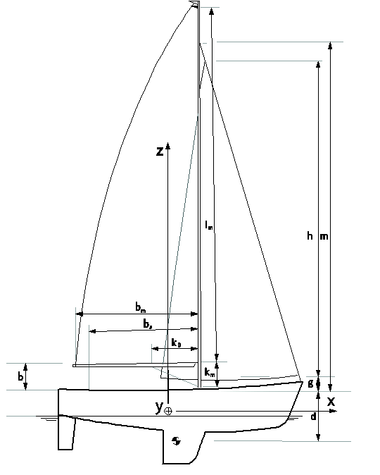
Figure 3.2.1 Parameter definition
2.3.4 General assumptions are:
- Drift forces act on the centre of gravity of the area projected by
the underwater body on the plane of symmetry of the boat even if this
underestimates the effectiveness of keel-fins compared to the canoe body.
- Heeling arm (a) is the (vertical) distance between centres of
gravity of sail(s) and lateral area of the underwater body.
- Between close hauled and close reach the sails act as foils. The leading edge
of the sail is kept parallel to the incoming (wind) flow.
2.3.5 For mainsails the following assumptions are made:
- A local co-ordinate system has been defined: u-v-w (see
Ch 3, 2.1 List of symbols)
- The resulting mainsail forces act perpendicular to the plane through mast and
boom. The in-plane forces are neglected.
- The mainsail forces are transferred by the leech and mast. The latter taking
fraction (1 - µ), the former µ of the total sail force.
- The sail exerts a distributed load on the mast. This is assumed to
be a distribution, naturally somewhere between the two extreme load patterns
(Figure 3.2.2 Two load-distributions to be examined) Neither of the two will be fully
valid but these cases represent the extremes. If the sail has large roach or
when the mast is so high that higher wind speeds can be expected at the upper
part of the mast, an elliptic distribution can be more realistic.
- Linear distribution, zero at the top and maximum at boom-height;
- Uniformly distributed load;
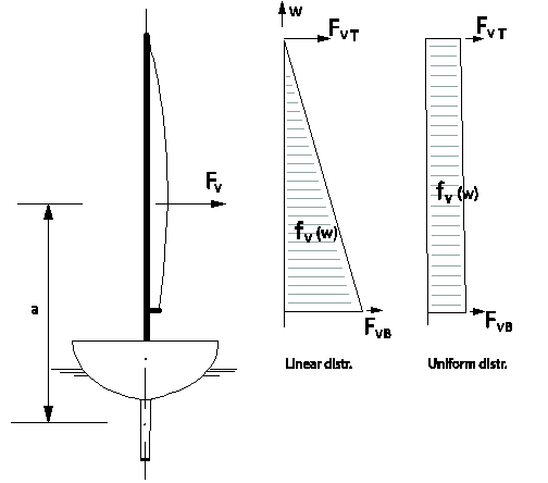
Figure 3.2.2 Two load-distributions to be examined
- The leech of the sail, carrying a fraction µ of the load, transfers this load to
the mast–top and end of the boom as point-loads. These loads are the transverse
components of the tension in the leach;
- Halyard force is equal, although opposed to the vertical force in the leech of
the mainsail
- Sagging of the sail’s leach controls the magnitude and direction of the
resulting forces in the mast-top and boom-end.
2.3.6 Summary of mainsail loads, acting on the mast, see
Figure 3.2.3 Sail-borne load-pattern, acting on the mast:
- Distributed load:
- Linearly distributed load yields:
Fv = M(ø)/a =
M(ø)/(d+b+lM/3);
Distributed load:
fv (w) = 2 (1-µ) Fv (1 – w /
lM) / lM ;
Point-load i.w.o. top of
mainsail: FvT = µ Fv /3
- Uniformly distributed load yields:
Fv = M(ø)/a =
M(ø)/(d+b+lM/2);
Distributed load:
fv (w) = (1-µ) Fv /
lM;
Point-load i.w.o. top of mainsail:
FvT = µ Fv /2
- Mast top, i.w.o. mainsail halyard sheeve: FwT = - 2 FvT
/αt
- In way of top of mainsail: FuT = - FvT bM
/(αt lM)
- In way of the gooseneck,
- as long as the boom vang is inactive:
FuB = FvT
bM /(αt
lM)
FwB = FvT (1-
bM /bS ) / αt
- When boom vang is taking all vertical loads, instead of
mainsheet:
FuB = FvT bM
/(αt lM) + FvT bM
/kM αt;
FwB =
FvT bM / kB
αt;
- Mast top: pre-tension/reaction force from backstay.
- Pretension of capshrouds: For ultimate loads however it is more realistic to
leave this out. Eventually to be applied in order to prevent collapse of the
mast i.w.o. the deck.
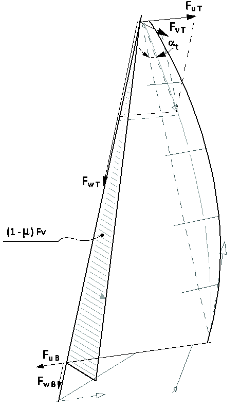
Figure 3.2.3 Sail-borne load-pattern, acting on the mast
2.3.7 A simplified approach is a reduced set of mainsail loads:
- Mainsail linearly distributed load 2.3.5 (a)i + mainsail halyard tension 2.3.5
(b) + backstay pre-tension/reaction 2.3.5 (e)
- Mainsail uniformly distributed load 2.3.5 (a)ii + mainsail halyard tension 2.3.5
(b) + backstay pre-tension/reaction 2.3.5 (e)
2.3.8 For headsails the following assumptions are made:
- The distribution of the headsail load over the height of the sail is varied in
the same way as was used for the mainsail;
- The total force on the headsail is transferred to the ship by the tack and clew
of the sail at deck-level and by the top of the sail at the mast.
- For the headstay the same load transfer assumptions hold as earlier mentioned
for the mainsail leech. The transverse component can only be generated by the
sag of the stay to leeward.
- The tangents to the luff of the sail are in one plane, namely in the direction
of the wind;
- The basis for the calculation is the righting moment M(øf). øf is the angle of
heel expected when only the foresail is set. Alternatively a certain fraction of
the total righting moment can be used.
2.3.9 For a summary of the headsail loads acting on the mast, see
Figure 3.2.4 Headsail forces, acting on the mast:
- At the connection of the forestay to the mast - FyH:
- Linearly distributed load yields:
FyH = M(ø)
(g+h/3)/m/(d+g+h/3);
- Uniformly distributed load:
FyH = M(ø)
(g+h/2)/m/(d+g+h/2);
FxH = FyH tg(τ –
β)/α
FzH = FyH /α
- (Pre-)tension forces from fore and aft stays;
- Pretension of shrouds. For ultimate loads however it is more realistic to leave
this out. Eventually to be applied in order to prevent collapse of the mast
i.w.o. the deck.
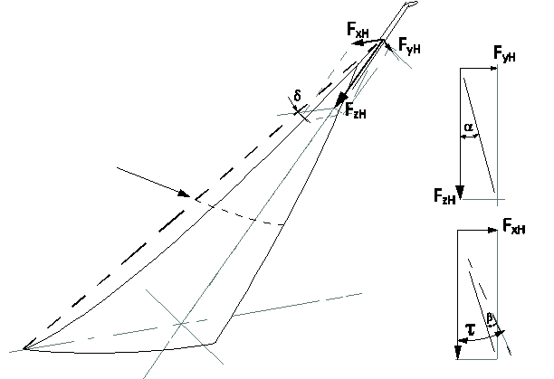
Figure 3.2.4 Headsail forces, acting on the mast
2.3.10 A simplified approach is a reduced set of headsail loads:
- Headsail linearly distributed load 2.3.8 (a)i + headsail halyard tension 2.3.8
(b)
- Headsail uniformly distributed load 2.3.8 (a)ii + headsail halyard tension 2.3.8
(b).
2.3.11 Genoa sails
Assumptions are made as follows:
- The load distribution of Genoa Sails can be based on the same considerations as
used for headsails.
2.3.12 Spinnakers
In absence of actual data assumptions can be made as follows:
- The load distribution over the height of the sail varies in proportion with the
distribution of the width of the sail.
- The total force is transferred to the ship by the tack and clew of the sail at
deck-level, each accounting for 30 per cent of the total force, with the
remaining 40 per cent of the force contributed by the top of the sail at the
mast.
2.3.13 Remarks on loads:
- On downwind courses foil-condition cannot be maintained as the sails will be
stalling. For the mainsail this means the loads are more or less evenly
distributed over the sail. Hence the fraction µ will be 0,5; load-distribution
in accordance with the sail; and boom vang forces eventually become important.
This condition may define the boom’s scantlings.
- Pre-tension on the shrouds is usually introduced in order to reduce the bending
moment of the mast i.w.o. the deck. Loss of pre-tension due to the vertical
components from fore- and back-stays, in conjunction with
hull-deformation/-sagging, then has to be shown not to exceed limits as set by
the mast-design/-scantlings.
- Loads for genoa sails and spinnakers.
2.4 Gaff type Rigs
2.4.1 Loads for gaff Type Rigs are to be evaluated on the basis of the method described for
Bermuda type rigs. The loads from the gaff and its associated halyards can be
derived based on the principles as previously described for Bermuda type rigs.
Topsails are used in general only above a mainsail, and the combination can be
considered as a mainsail, as described under the Bermuda type rig.
2.5 Square sail type Rigs
2.5.1 In square sail type rigs loads are to be applied as point loads, distributed based on
the area of sail set.
2.5.2 Wind generated loads carried by the masts from the sails or to staysail stays may be
evaluated using typical expressions for the lift on aerofoil sections:
Where
|
C
|
= |
CL, lift coefficient or CD, drag
coefficient, as appropriate |
2.5.3 The mean lift coefficient (Ct) from sails assuming the optimum angle of
attack is generally to be taken as:
- 1,1 for staysails
- 1,2 for fore and aft sails on masts with booms,
- 1,4 for square sails.
2.5.4 The drag coefficient for masts, standing rigging and yards with furled sails is to be
taken as 1,2.
2.5.5 Application of drag is generally only required for the survival condition with bare
poles and a very high wind speed.
2.5.6 Staysail loads induce catenary response in the stays, and equilibrium between the
stay sag, applied sail luff load and stay tension has to be maintained. There
clearly is a practical limit as to how much sag can be removed from a staysail stay
before abnormally high stay tensions are induced. Over the years there has been much
argument and debate over a suitable value of stay sag, and it is suggested that the
likely value lies somewhere between 3 per cent for genoa sails with high performance
and 6 per cent of the stay length. For the purposes of calculation for traditional
square rigs, a assumed stay sag within these boundaries is used to develop staysail
stay tensions. Hence, staysail stay tension is approximated to:
2.5.7 In modern rigs, where less stay sag is usually permitted, higher values for tension
are to be expected.
2.5.8 The vector components of the stay tensions are added to the loading in the analysis
model at the tack point. At the bowsprit MPS or Spinnaker are usually attached
without any pretension loads. For analysis of the loads in the staysail stays, the
tension induced by the staysail must be added to the F.E. analysis result in order
to obtain the total stay tension. The best solution would be to model the entire
stay with several link elements in order to also simulate the sag behaviour of the
stay.
2.5.9 Although running rigging is not included in the classification process, significant
additional loads are generated on the masts and bowsprit at the running rigging
attachment points. The mass of the halyards and sails also contribute to the axial
loading in the masts and, more importantly, to the lateral forces applied to the
masts as a result of ship motion induced acceleration.
2.5.10 The detailed methods of load application to the finite element model are not
presented in this guidance note, as it is considered that experienced analysis would
apply suitable techniques which would generally be discussed and agreed with the
Certifying Authority.
2.6 Guidance on damage cases
2.6.1 The document ‘Large Yachts: Examination of Carbon Fibre Masts and Spars’ July 2011,
as issued by the UK Maritime and Coastguard Agency, gives advice for the evaluation
of damage cases, which may be of use for the Design Evaluation. The document also
states:
- 6.4.1 In order to simulate the structural behaviour of a rig, a
Finite Element Analysis of a rig model consisting of
beam and truss elements is performed. This model
represents the global characteristics of a rig
system. For any particular rig, the real geometry
and stiffness of major global components such as
mast tube and standing rigging is replicated in the
model. Computations include pre-tensioning, load
simulation of in-service loads such as quasi-static
sail loads, and pertinent structural accelerations.
- 6.5.1 The FEA tasks should be performed by qualified engineers
experienced in modelling composite materials.
- 6.5.2 Modelling experience is required to ensure the relevant
coordinate system is correctly used (i.e. global,
ply, laminate based, or element based). The approach
used should be documented by the analyst.
- 6.5.5 Whenever possible, a decision to use 2D shell analysis or
3D solid analysis methods should be made depending
on the level of significance that through thickness
stresses have on the investigation. The approach and
reasons for method selection should be documented by
the analyst.
- 6.7.2 Global analysis should be used to identify the potential
for failures such as global buckling, shear
stiffness of spar tubes, thin wall buckling, and
other stability evaluations used in the design
process. The critical loads for thin wall buckling
can be derived from sub-models.
|