
Section
3 Assessment of the stack
3.1 Assessment of the stack deformation
3.1.1 The deformation of the stack is solved using matrix methods. The resulting
deformation can be used to derive the forces in the container end wall, corner
posts, twistlocks and lashing devices using Hooke’s law.
F = K ·δ + C
δ = K-1 · (F - C)
where
F = the applied nodal force matrix, in kN
K = the stiffness matrix of the stack and securing devices, in kN/mm
C = the twistlock force matrix of the stack, in kN, which is non zero when a
twistlock is open
δ = the nodal displacement matrix, in mm
3.1.2 The stack stiffness matrix and twistlock force matrix are dependent on
the state of the twistlock and lashing devices. This implies that the solution has a
non-linear component requiring an iteration technique to solve.
3.2 Boundary conditions
3.2.1 To invert the stiffness matrix adequate constraints are to be imposed. It is
sufficient to fix the base of the stack and the base of the lashing bridge. The
boundary constraint can be included by imposing a large value along the diagonal of
the stiffness matrix at the degrees of freedoms constrained.
3.3 Forces in the container
3.3.2 The racking force of the container panels is calculated from the transverse shear
deformation and the shear stiffness.
3.3.3 The vertical force in the corner post is to be calculated from the
compression of the post plus the vertical force due to shear in the end wall acting
on the post.
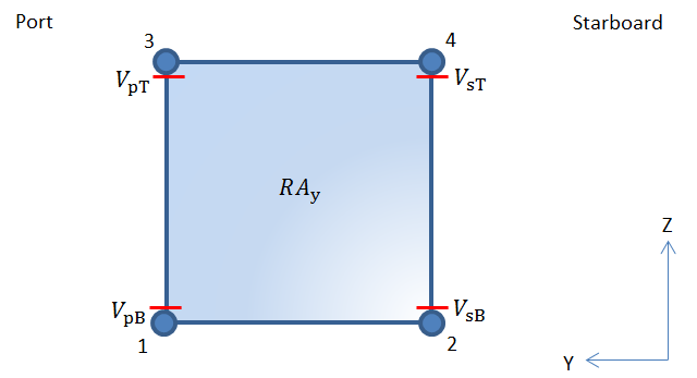
Figure 1.3.1 Container end wall showing
locations for evaluating corner post forces
3.3.5 The maximum compressive force in each corner post of the container must
not exceed the vertical forces at each top corner casting and in each corner post,
compression, specified in Pt 3, Ch 14 Cargo Securing Arrangements, Pt 3, Ch 14, 9.4 Allowable forces on containers, fittings and lashing devices 9.4.12.
The maximum tensile force in each corner post of the container must not exceed the
vertical forces at each top corner casting, tension, specified in Pt 3, Ch 14 Cargo Securing Arrangements, Pt 3, Ch 14, 9.4 Allowable forces on containers, fittings and lashing devices 9.4.12.
3.3.8 The allowable forces for container end walls are shown in Table 1.3.1 Allowable forces for containers.
Table 1.3.1 Allowable forces for containers
| Name
|
Force component
|
Allowable
|
| Tension
|
Compression
|
| Racking force
|
RAy
|
RAyAllowable
|
| Corner post
force
|
VsT
|
VTTAllowable
|
VTCAllowable
|
| VpT
|
| VsB
|
| VpB
|
|
where
RAyAllowable = the allowable
racking force on the container end, in kN, from Pt 3, Ch 14 Cargo Securing Arrangements,
Pt 3, Ch 14, 9.4 Allowable forces on containers, fittings and lashing devices 9.4.12.
VTTAllowable = the allowable
vertical force at each top corner casting, tension, in kN, from
Pt 3, Ch 14 Cargo Securing Arrangements,
Pt 3, Ch 14, 9.4 Allowable forces on containers, fittings and lashing devices 9.4.12.
VTCAllowable = the allowable
vertical force at each top corner casting and in each corner
post, compression, in kN, from Pt 3, Ch 14 Cargo Securing Arrangements,
Pt 3, Ch 14, 9.4 Allowable forces on containers, fittings and lashing devices 9.4.12.
|
3.4 Forces in the twistlock
3.4.1 From the calculated displacements of the twistlock nodes, the twistlock
vertical forces and twistlock shear forces can be calculated. Figure 1.3.2 Twistlock forces shows the location points where the forces are
recorded.
3.4.2 The vertical force in the twistlock is to include the vertical forces from the
triangular shear elements for both port and starboard twistlocks.
3.4.3 The calculated twistlock shear force is to be increased by 10 per cent
due to misalignment, corrosion and design tolerances before comparing to the Safe
Working Load (SWL).
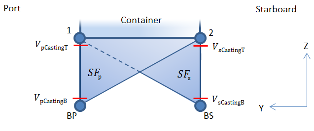
Figure 1.3.2 Twistlock forces
3.4.4 The maximum vertical compressive force in the twistlock is not to be greater than the
allowable vertical forces at each bottom corner casting, compression and the maximum
vertical tensile force in the twistlock is not to be greater than the allowable
vertical corner pull-out force at each bottom corner casting.
3.4.5 The twistlock tensile load is to be less than the SWL.
3.4.7 The allowable forces for twistlocks are shown in Table 1.3.2 Allowable forces for twistlocks.
Table 1.3.2 Allowable forces for twistlocks
| Name
|
Force component
|
Allowable
|
| Tension
|
Compression
|
| Twistlock
shear force
|
SFs
|
TLSFAllowance
|
| SFp
|
| Twistlock
axial force
|
VsCastingT
|
TLTAllowance
VCTAllowable
|
VCCAllowable
|
| VpCastingT
|
| VsCastingB
|
| VpCastingB
|
|
where
TLSFAllowance = the allowable
shear force on the twistlock, in kN, from Pt 3, Ch 14 Cargo Securing Arrangements ,
Pt 3, Ch 14, 3.3 Prototype testing 3.3.1
TLTAllowance = the allowable
tensile force on the twistlock, in kN, from Pt 3, Ch 14 Cargo Securing Arrangements,
Pt 3, Ch 14, 3.3 Prototype testing 3.3.1
VCTAllowable = the allowable
vertical force at each bottom corner casting, tension, in kN,
from Pt 3, Ch 14 Cargo Securing Arrangements,
Pt 3, Ch 14, 9.4 Allowable forces on containers, fittings and lashing devices 9.4.12.
VCCAllowable = the allowable
vertical force at each bottom corner casting, compression, in
kN, from Pt 3, Ch 14 Cargo Securing Arrangements,
Pt 3, Ch 14, 9.4 Allowable forces on containers, fittings and lashing devices 9.4.12.
|
3.5 Forces in the lashing device
3.5.1 From the calculated displacements of the lashing rod nodes, the lashing
rod force and applied casting forces can be calculated.
3.5.2 The forces and force components in the lashing devices must not be
greater than the allowable lashing forces on the corner castings and the SWL of the
lashing device.
3.5.6 The allowable forces for lashing devices are shown in Table 1.3.3 Allowable forces for lashing devices.
Table 1.3.3 Allowable forces for lashing devices
| Name
|
Component
|
Force
|
Allowable
|
| Lashing rod force
|
Fr
|
LRAllowable
|
| Container casting force
|
Transverse
|
FCastingY
|
LRCYAllowable
|
| Vertical
|
FCastingZ
|
LRCZAllowable
|
| End Wall
Plane
|
FCasting
|
LRCAAllowable
|
|
where
LRAllowable = the allowable tensile
force of the lashing rod, in kN, from Pt 3, Ch 14 Cargo Securing Arrangements,
Pt 3, Ch 14, 3.3 Prototype testing 3.3.1
LRCYAllowable = the allowable
horizontal force from lashing on container casting acting
parallel to the end face, in kN, from Pt 3, Ch 14 Cargo Securing Arrangements,
Pt 3, Ch 14, 9.4 Allowable forces on containers, fittings and lashing devices 9.4.12.
LRCZAllowable = the allowable
vertical force from lashing on lower container casting acting
parallel to the end face, in kN, from Pt 3, Ch 14 Cargo Securing Arrangements,
Pt 3, Ch 14, 9.4 Allowable forces on containers, fittings and lashing devices 9.4.12.
LRCAAllowable = the allowable
resultant force from lashing on container casting acting
parallel to the end face, in kN. For lashings secured to the top
container corners it is taken as the resultant force from
para-lashing on upper container casting acting parallel to the
end or side face, taken from Pt 3, Ch 14 Cargo Securing Arrangements,
Pt 3, Ch 14, 9.4 Allowable forces on containers, fittings and lashing devices 9.4.12
For lashings secured to the bottom corner castings it is taken
as 300 kN, from Pt 3, Ch 14 Cargo Securing Arrangements,
Pt 3, Ch 14, 9.4 Allowable forces on containers, fittings and lashing devices 9.4.12.
|
|