
Section
2 Modelling of the container stack
2.1 Stack assembly
2.1.1 The stack behaviour is governed by four main element types and their stiffness
properties:
- container element;
- twistlock element;
- lashing element; and
- lashing bridge element.
2.1.2 Stacks comprise of containers stacked on top of each other with four twistlocks
positioned at each corner of the container base. For assessment of the stack ends,
only the end face of the container and the two twistlocks below are included in the
model.
2.1.3 Lashings connect the container corners to the lashing bridge or the upper deck.
Lashings at the forward end of the container are assumed not to influence the aft
end of the container. This method, therefore, does not include the impact of the
longitudinal force of the lashing on the container posts.
2.1.4 The average stiffness of the lashing bridge is used and the impact of adjacent stacks
is ignored. This simplifies the calculation and allows for each stack to be assessed
independently.
2.1.5 Each stack element is associated with a set of degree of freedoms that govern the
force distribution and deformation behaviour of the member. The stiffness matrix of
the stack is assembled by coupling the degrees of freedom of the stack elements.
2.1.6 The forces are applied to the associated degrees of freedom, deforming the stack and
distributing the applied load through the members. For the assessment of the stack
ends, any longitudinal loads are to be converted to vertical forces applied to the
container corners based on the reaction moments required to balance the stack.
2.1.7 It is assumed the base of the stack is fixed relative to the base of the lashing
bridge, and these degrees of freedom are constrained.
2.1.8 The stiffness matrix of the elements is symmetric and only one side of the matrix is
presented in this guidance Note unless stated otherwise.
2.2 Container stiffness
2.2.2 Figure 1.2.1 Container end wall shows the mathematical model of the container end
element for a two-dimensional assessment. Element E is the shear only member,
elements B and D are the corner post members and elements A and C are the top and
bottom horizontal post members. All five members are coupled at the four corner
nodes, nodes 1 to 4.
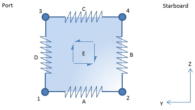
Figure 1.2.1 Container end wall
2.2.3 The container element is modelled with a shear only element for the end
wall and four spring elements to represent the axial strength of the corner posts
and horizontal bars.
2.3 Twistlock stiffness
2.3.1 Inherent in the twistlock design is a need for play in order to be able
to fit the device. This play allows easy installation of the twistlocks, but this
also means that vertical lifting of the top container occurs before the twistlock
comes in to tension. Twistlocks therefore have three states; see Table 1.2.1 Twistlock separation and
states. This vertical lifting distance is
referred to as twistlock separation. If this separation occurs, then it can
significantly increase the transverse stack deformation and the forces in the
lashing devices, see
Figure 1.2.3 Twistlock force extension
curve.
The assessment of the effects of twistlock separation is particularly critical for
external lashing arrangements.
Table 1.2.1 Twistlock separation and
states
| State
|
Figure
|
Description
|
| (a) Twistlock closed
|
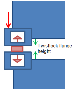
|
Twistlock closed and in compression.
The distance between the container castings is equal
to the twistlock flange height.
|
| (b) Twistlock open
|
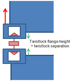
|
Twistlock open and in tension.
The distance between the container castings is equal
to the twistlock flange height + twistlock separation.
|
| (c) Twistlock float
|
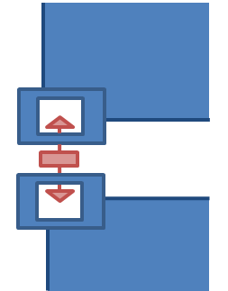
|
Float condition with zero axial force.
The distance between the container castings is in
between closed and open state.
This state will not occur above the lashing
points.
|
2.3.2 Shear deformation of the twistlocks can be ignored.
2.3.3 Figure 1.2.2 Port and starboard
twistlocks shows the mathematical model of the port and
starboard twistlocks. Each twistlock includes a shear only triangular member to
resist the shear force and a vertical spring member to resist vertical axial
loads.
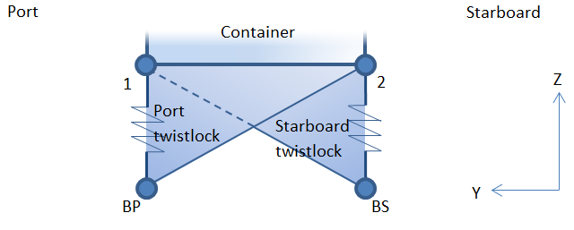
Figure 1.2.2 Port and starboard
twistlocks
2.3.4 The port twistlock comprises of a triangular shear element connected to
node 1, node 2 and node BP, and an axial spring connected to node 1 and node BP.
2.3.5 The starboard twistlock is a mirror of the port twistlock and comprises
of a triangular element connected to node 1, node 2 and node BS, and an axial spring
element connected to node 2 and node BS.
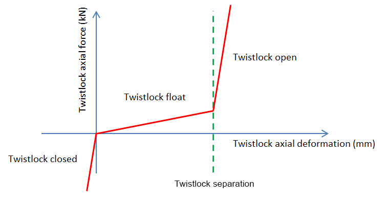
Figure 1.2.3 Twistlock force extension
curve
2.4 Lashing devices stiffness
2.4.2 The lashings are assumed to be constrained in the longitudinal direction at both the
fixed end and the container end.
2.4.3 Figure 1.2.4 Lashing device shows the mathematical model of the lashing devices.
Each lashing can be connected to a corner of a container and a fixed part of the
hull or lashing bridge tier.
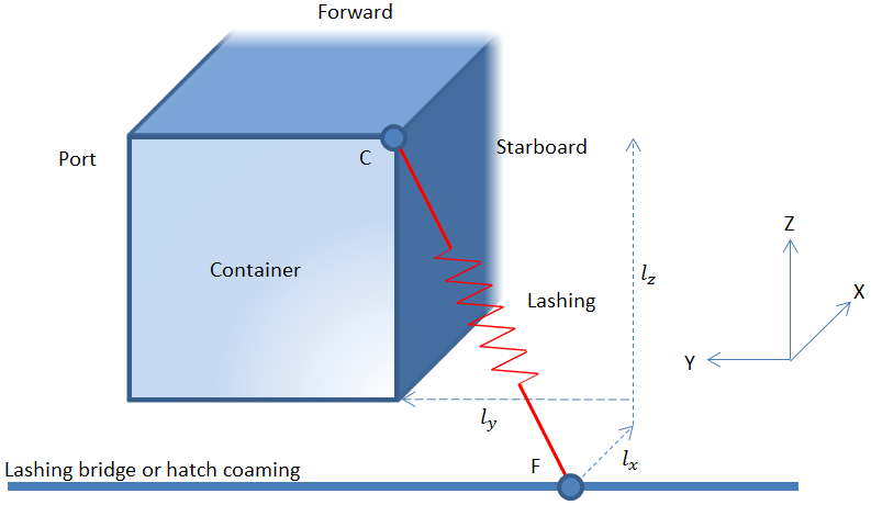
Figure 1.2.4 Lashing device
2.4.4 The lashing rod is mathematically modelled as a spring connecting the
container corner, node C, to a fixed point, node F. The spring can be removed when
in compression.
The stiffness of the lashing can be calculated as:
where
|
KLR |
= |
the stiffness of the lashing, in kN/mm2 |
|
Eeff |
= |
the effective modulus of elasticity of the lashing, in
kN/mm2 |
|
Eeff |
= |
Er when the lashing is in tension |
|
Eeff |
= |
0 kN/mm2 when the lashing is in compression |
|
Ar |
= |
the effective lashing rod cross-sectional area, in mm2 |
|
lr |
= |
the length of the lashing rod, in mm |
|
lr |
= |
 |
where
|
lx |
= |
the longitudinal component of the lashing rod from the lashing bridge, in
mm, positive forward |
|
ly |
= |
the transverse component of the lashing rod from the lashing bridge, in mm,
positive to port |
|
lz |
= |
the vertical component of the lashing rod from the lashing bridge, in mm,
positive upwards |
2.5 Lashing bridge stiffness
2.5.1 Where lashing devices are attached to a lashing bridge, the lashing bridge transverse
stiffness is to be taken into account and may be modelled with rod elements. For
lashing bridge designs with multiple lashing platforms, a lashing bridge rod element
is required for each platform. All the lashing bridge rod elements are to be
connected in series. The bottom of the lashing bridge can be assumed to be rigidly
fixed.
2.5.2 The lashing bridge tier is assumed to be fixed in the vertical and longitudinal
direction. The bottom of the lashing bridge is assumed to be fixed in all degrees of
freedom.
2.5.3 Figure 1.2.5 Assembly of a three tier
lashing bridge shows the mathematical model of a three tier lashing
bridge. The transverse location of the nodes is not important and only included for
demonstrative purposes. Lashings attached to tier 2 would be connected to node LB2,
and lashings attached to tier 3 will be connected to node LB3.
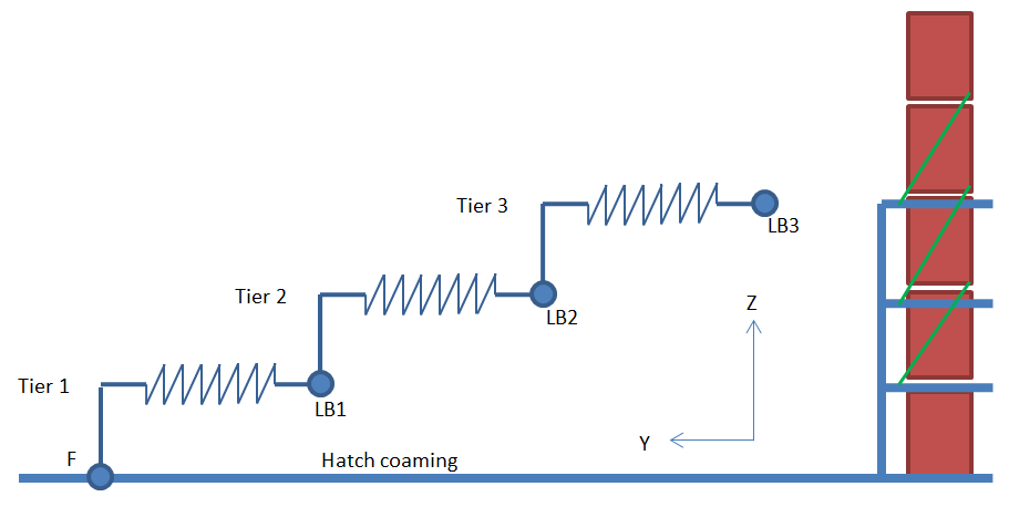
Figure 1.2.5 Assembly of a three tier
lashing bridge
2.5.4 A single lashing bridge tier can be mathematically modelled as a
horizontal spring. The spring stiffness is set to the transverse spring stiffness of
the lashing bridge as defined in Pt 3, Ch 14 Cargo Securing Arrangements,
klby.
|
| Copyright 2022 Clasifications Register Group Limited, International Maritime Organization, International Labour Organization or Maritime
and Coastguard Agency. All rights reserved. Clasifications Register Group Limited, its affiliates and subsidiaries and their respective
officers, employees or agents are, individually and collectively, referred to in this clause as 'Clasifications Register'. Clasifications
Register assumes no responsibility and shall not be liable to any person for any loss, damage or expense caused by reliance
on the information or advice in this document or howsoever provided, unless that person has signed a contract with the relevant
Clasifications Register entity for the provision of this information or advice and in that case any responsibility or liability is
exclusively on the terms and conditions set out in that contract.
|
 |
|