7.2 Furnace Temperature Thermocouples
Clasification Society 2024 - Version 9.40
Statutory Documents - IMO Publications and Documents - Resolutions - Assembly - IMO Resolution A.754(18) – Recommendation on Fire Resistance Tests for “A”, “B” and “F” Class Divisions – (Adopted on 4 November 1993) - Annex - Recommendation on Fire Resistance Tests for “A”, “B” and “F” Class Divisions1 - 7 Instrumentation - 7.2 Furnace Temperature Thermocouples

7.2 Furnace Temperature Thermocouples

7.2.1 Design

 The furnace temperature should be measured by thermocouples as shown in Figure 4. They may be either thermocouples of bare-wire design or sheathed thermocouples having an equivalent response time to that of bare-wire thermocouples. The bare-wire thermocouples should have a wire diameter of between 0.75 and 1.00 mm and a welded or crimped junction. At least 25 mm of wire should project from the insulation. Bare-wire thermocouples should be checked at least after every 20 h of use, and stainless-steel-sheathed thermocouples should be checked at least after every 50 h of use, to establish their accuracy and sensitivity. If any doubt exists as to their serviceability, they should be replaced.

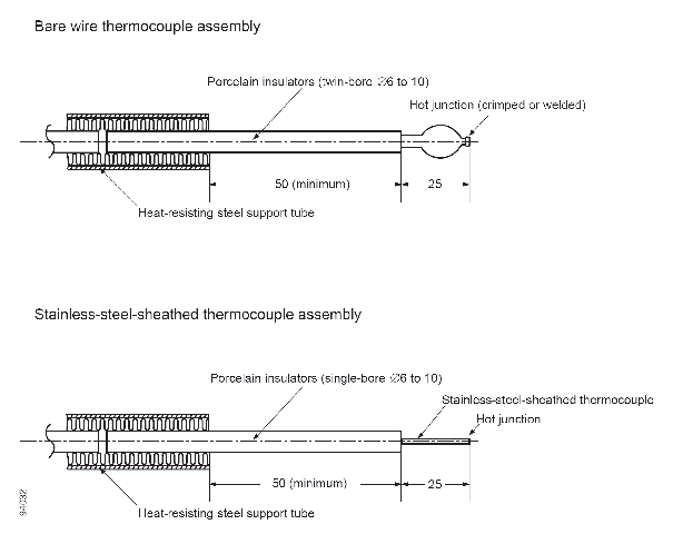
Figure 4 Furnace thermocouple assembly

7.2.2 Number

 At least six furnace thermocouples should be provided for the specimens given in section 2. For specimens larger than specified in section 2, additional thermocouples should be provided in the proportion one per 1.5 m2 of the specimen area. In the case of a door assembly, specimen area refers to the entire bulkhead construction with the door fitted.

7.2.3 Positioning

 The thermocouples employed to measure the temperature of the furnace should be uniformly distributed so as to give a reliable indication of the average temperature in the vicinity of the specimen. At the commencement of the test the measuring junctions should be 100 mm from the face of the specimen and they should be maintained at a distance of 50 mm to 150 mm during the test. The method of support should ensure that thermocouples do not fall away or become dislodged during the test. Where it is convenient to pass thermocouple wires through the test construction, then the steel support tube should not be used. The hot junctions of the thermocouples should not be located at positions within the furnace where they are subject to direct flame impingement.

7.2.4 Connection

 The thermocouple wire should be either continuous to the recording instrument or suitable compensating wire should be used with all junctions maintained as near as possible at ambient temperature conditions.


Copyright 2022 Clasifications Register Group Limited, International Maritime Organization, International Labour Organization or Maritime and Coastguard Agency. All rights reserved. Clasifications Register Group Limited, its affiliates and subsidiaries and their respective officers, employees or agents are, individually and collectively, referred to in this clause as 'Clasifications Register'. Clasifications Register assumes no responsibility and shall not be liable to any person for any loss, damage or expense caused by reliance on the information or advice in this document or howsoever provided, unless that person has signed a contract with the relevant Clasifications Register entity for the provision of this information or advice and in that case any responsibility or liability is exclusively on the terms and conditions set out in that contract.