3.3.1 The structure is loaded in pure bending. The surface warp at the end faces of the
model is suppressed.
3.3.2 The bending moment is applied to the central node on the crankshaft axis. This node
acts as the master node, with six degrees of freedom, and is connected rigidly to
all nodes of the end face.
3.3.3 The boundary and load conditions are valid for both in-line and V- type engines.
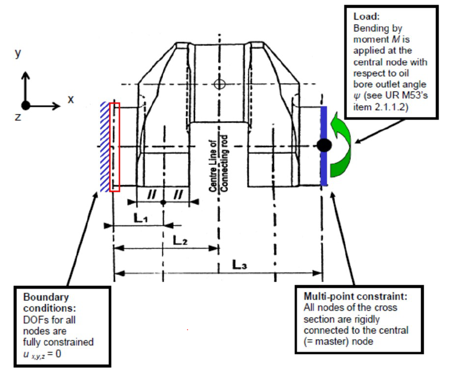
Figure 4.3.2 Boundary and load conditions for the pure bending load case
3.3.4 For all nodes in the oil bore outlet, principal stresses are obtained and the maximum
value is taken for subsequent calculation of the SCF:
where the nominal bending stress σ
N referred to the crankpin is calculated
per the “Calculation of bending stresses” sub- Section of the applicable Rules with
bending moment
M: