5.1 General
This section describes the details of the release gear system. Read this
section carefully for safe operation. This release gear system consists of fore and
aft hooks, a release handle near the steering console, a hydrostatic unit and the
associated cables (see figure 5.1).
The releasing operation of the hooks is conducted at the release handle
near the steering console through the control cables terminating at the fore and aft
hooks. The interlock system including the hydrostatic interlock unit is provided to
prevent the release of the hooks when the boat is not waterborne.
The system also has an on-load release function which makes it possible
to over-ride the interlock by the hydrostatic unit. Incorrect on-load release
operation may cause fatalities and due precautions should be taken for this
operation.
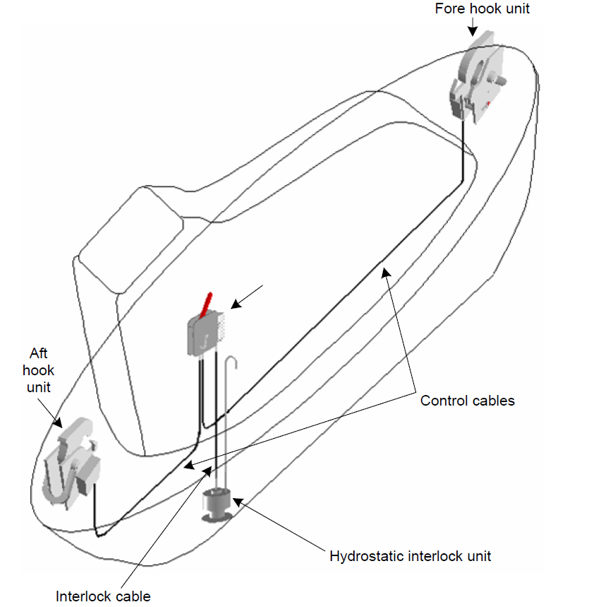
Figure 5.1 Schematic of release gear system
5.2 Fore and aft hook units
5.2.1 Structure and parts names
The structure and parts names of the fore and aft hooks are shown in figures 5.2.1.1
and 5.2.1.2. The fore and aft hooks are generally identical except for the direction
of installation.
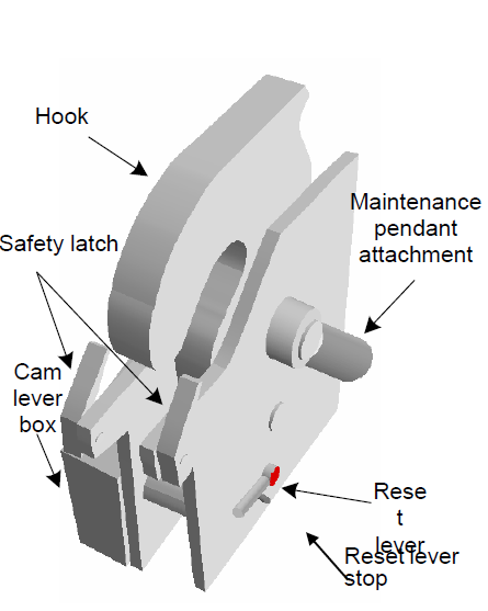
Figure 5.2.1.1 Perspective of the hook unit
|

Figure 5.2.1.2 Internal view of the hook unit
|
5.2.2 Releasing
When the release handle near the steering console is pulled, the cam lever pin is
turned by the control cable and the lock piece is then made free. Finally, the hook
is turned and released (see figure 5.2.2).
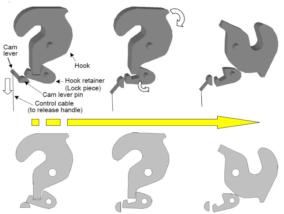
Figure 5.2.2 Release principle of the hook unit
5.2.3 Resetting
After the resetting of hooks, the posture of each hook is held by the lock piece and
the lock piece is locked by the cam lever pin with the reset lever. To ensure the
proper resetting of the fore and aft hooks, the procedures described in paragraph
4.1 should be followed. The fore and aft reset levers must be operated
simultaneously. After simultaneous resetting of the hooks, the release handle near
the steering console also returns to the closed position (see figure 5.2.3).
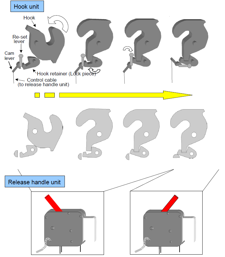
Figure 5.2.3 Reset principle of the hook unit
5.3 Release handle unit
5.3.1 Structure and parts names
The structure and parts names of the release handle are shown in figures 5.3.1.1 and
5.3.1.2.
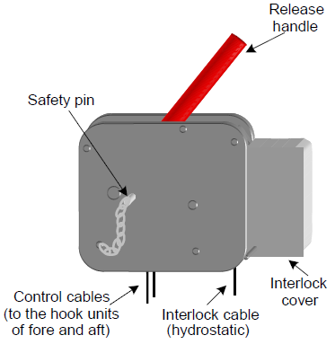
Figure 5.3.1.1 Perspective of the release handle
unit
|
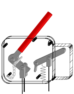
Figure 5.3.1.2 Internal view of the release handle
unit
|
5.3.2 Operation
When the lifeboat is fully waterborne, the lifeboat can be released by removing the
safety pin and then pulling the release handle fully and quickly to the open
position (off-load release). The lifeboat can also be released by the same operation
of the release handle even though the lifeboat is not fully waterborne, by opening
the interlock cover and lifting up the interlock lever. This over-rides the
interlock function of the hydrostatic interlock unit (on-load release).
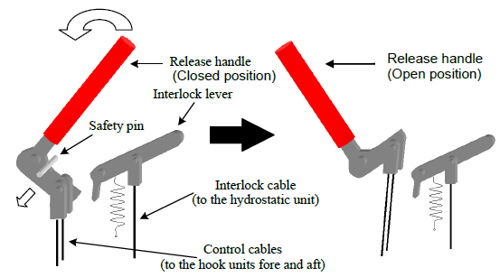
Figure 5.3.2 Operation procedure of the release handle
5.4 Hydrostatic interlock unit
5.4.1 Structure and parts name
Structure and parts names of the hydrostatic interlock unit are shown in
figures 5.4.1.1 and 5.4.1.2.
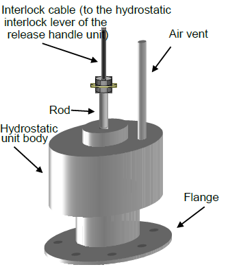
Figure 5.4.1.1 Perspective of the hydrostatic interlock
unit
|

Figure 5.4.1.2 Internal view of the hydrostatic interlock
unit
|
5.4.2 Operation
When the lifeboat is fully waterborne, the
hydrostatic interlock unit pushes up the interlock lever through the interlock cable
by the water lifting the float and thus allowing the release handle to be operated.
Contrary to this, operation of the release handle is not allowed by the hydrostatic
interlock unit when the lifeboat is not fully waterborne.

Fig. 5.4.2 Schematic diagram of the interlock