3.1
Pressure
transducers
The pressure transducers, signal conditioning, and recording
system should have a frequency response range which will measure the
impulsive pressures arising from cavitation. An upper frequency response
of about 5,000 Hz should be adequate for most purposes.
Corrosion
resistant pressure transducers should be used. Ideally the sensitive
membrane of the transducer should be flush with the outer hull surface
in order to avoid unwanted pressure harmonics. The design of available
transducers and fitting sometimes make this difficult to achieve in
practice.
3.2
System calibration
The pressure transducers and complete recording system should
be calibrated before and after the measurements.
3.3
Pressure
components
The hull surface pressure comprises two components. The first
is the direct radiated pressure from the propulsor and the second
is a self induced pressure resulting from the vibration of the transducer
mounted on the hull.
To separate these two components
it is necessary to measure the vibration at the pressure transducer
locations. This data, via suitable transformation methods, can be
used to estimate the self-induced pressure components in terms of
amplitude and phase at the transducer location.
3.4
Measurement
locations
The number of pressure transducers should, ideally, be between
five and seven. For a right-handed propeller of diameter D, four pressure
transducers should be placed at 0.05D to starboard of the shaft centreline,
Figure 2.3.1 Propeller pressure measurement positions
. The longitudinal positions
should be in the measurement reference plane shown in
Figure 2.3.1 Propeller pressure measurement positions
, at intervals of 0.15D,
starting at 0.10D aft of the propeller tip plane. At the plane 0.05D
ahead of the propeller tips additional transducers may ideally be
placed at 0.10D to port and 0.15D and 0.25D to starboard. The mirror
image of this pattern should be applied for a left handed propeller.
For ships with significant areas of shell plating aft of the
propeller plane, pressure transducers may also be required to be located
at distances up to 2D aft of the propeller plane in line with the
principal tip vortex activity in the wake peak.
3.5
Phase marker
A phase marker or angular position indicator should be fitted
to the inboard shafting. It is convenient if this coincides with a
particular blade at a known angular position of the propeller.
3.6
Visual observation
Consideration should also be given to fitting viewing ports
in the hull to allow boroscopes or video cameras and stroboscopic
lighting to be used for observation in cases where severe cavitation
occurs.
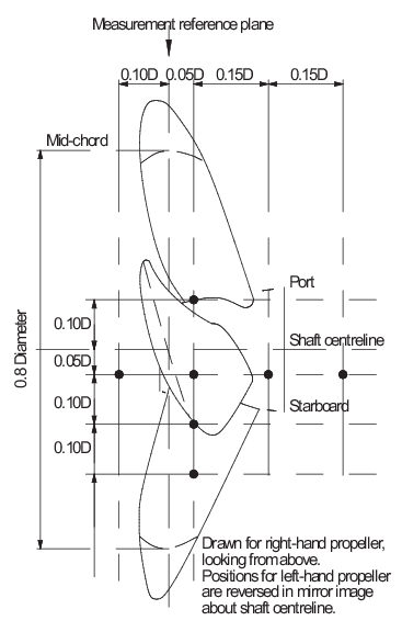
Figure 2.3.1 Propeller pressure measurement positions