1.2.1 A meter designed to operate over a wide
range of oil content should measure the true oil content of the sample
entering the meter during each test within ±10 ppm or ±10%,
whichever is the greater, and testing should be performed in accordance
with the procedures detailed in paragraphs 1.2.5 to 1.2.18 of this
specification. The accuracy should remain within these limits in the
presence of contaminants other than oil and ±10% variations
from design criteria with respect to power (electricity and compressed
air).
1.2.2 A diagrammatic arrangement of a test rig
for evaluating the performance of oil content meters is given in figure 1. The accuracy of the oil
content meter should be determined by comparing its readings with
a known flow of oil injected into a known flow of water. The grab
samples taken should be analysed in a laboratory by the method described
in paragraph 1.3 of this specification. The results of the laboratory
analysis will be used for correlation and to indicate sampling and
test equipment variability. The water flow rate should be adjusted
so that the entire oil-water flow passes through the oil content meter,
except the intermittent grab sample stream. Special care should be
given to keep, continuously, a constant oil content in the water that
flows into the meter. The oil and contaminant metering pumps should
be adjusted to deliver a steady flow. If oil injection becomes intermittent
at low concentrations, the oil may be premixed with water to provide
continuous flow, if absolutely necessary. The oil injection point
should be immediately upstream of the oil content meter inlet to minimize
time lags caused by the sample system. Wherever No.2 crude oil is
specified in particular tests, a similar crude oil may be substituted,
provided that the oil selected is used throughout the tests.
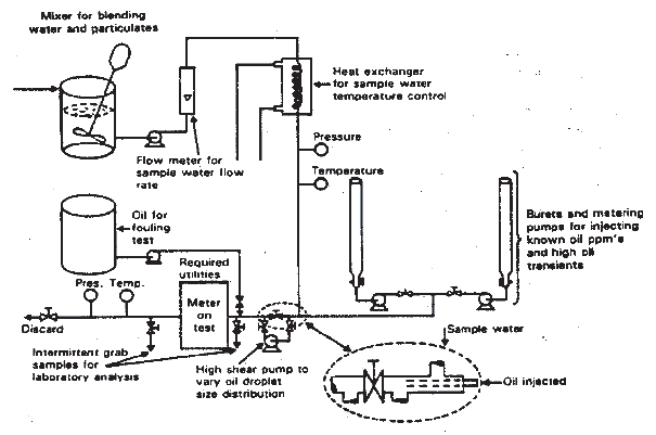
Test rig
1.2.3 The sampling arrangement should be such
that a representative homogeneous sample is obtained under all conditions
of operation and under all operational proportions of oil content.
The sample should be obtained from the full flow through the meter,
but when this is impracticable, the sampling arrangements shown in figure 2 should be used. Special
care should be taken in collecting and preserving the sample to ensure
validity of the resultant findings.
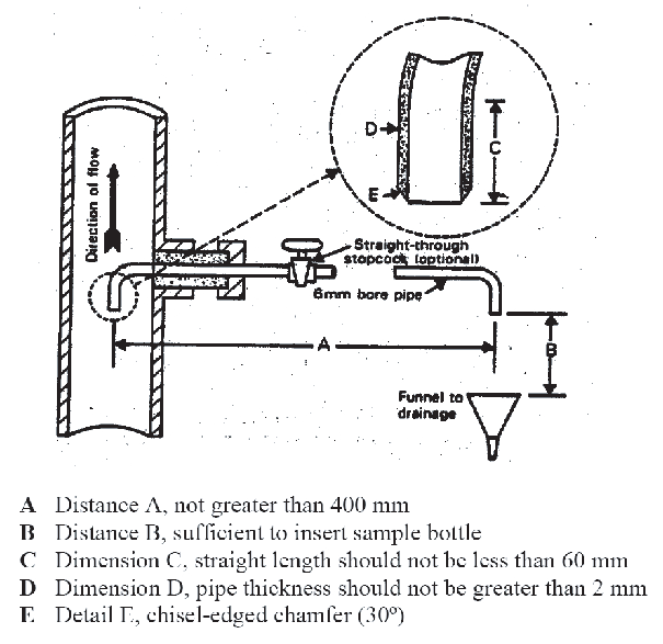
Alternative sampling arrangement in test rig
1.2.4 Should the oil content meter incorporate
a filter or other device for removing solid contaminants from the
mixture to be tested, such a device should be regarded as part of
the oil content meter and be connected during all the tests. After
completion of the contaminant, tests referred to in paragraph 1.2.10
the device used to remove solid contaminants from the mixture should
be opened up and the residues inspected to ascertain that they do
not contain significant amounts of oil.
1.2.5
Calibration and zero test. The
oil content meter should be calibrated and zeroed in accordance with
the manufacturer's instructions. It should then be tested using the
No.2 crude oil at the following concentrations in ppm 0, 15, 50, 100,
200 and at intervals of 200 up to the maximum of the meter's highest
range. A complete calibration curve should be constructed. Each concentration
test should last for 15 min. After each concentration test the meter
should be run on oil-free water for 15 min and the reading noted.
The instrument should not be re-calibrated in spite of any movement
from zero.
1.2.6
Response tests. Different oil
types - After calibration in the previous test, the oil content meter
should be tested at concentrations of 15 ppm, 150 ppm and 90% of the
maximum full-scale with the following oils. Additional concentrations
may be added if required to construct a complete calibration curve
for each of the following oils:
|
For CRUDE OILS¹
|
|
Category of Oil
|
Categories Represented
|
Parameters Tolerance
|
| 1
|
Density – low
|
Density*: 790.0-800.0
|
| Viscosity – low
|
Kinematic viscosity**: 2.65 ±
5%
|
| Pour Point – very low
|
Cloud point***: -2 ± 3°C
|
| General description – mixed
base
|
|
| 2
|
Density – medium
|
Density: 852.0-862.0
|
| Viscosity – medium
|
Kinematic viscosity: 10.19 ±
5%
|
| Pour point – low
|
Cloud point: -5 ± 3°C
|
| General description – mixed
base
|
|
| 3
|
Density – high
|
Density: 884.0-894.0
|
| Viscosity – medium
|
Kinematic Viscosity: 12.9 ±
5%
|
| Pour point – low
|
Cloud point: 5 ± 3°C
|
| General description –
naphthenic
|
|
| 4
|
Density – very high
|
Density: 947.0-957.0
|
| Viscosity – very high
|
Kinematic Viscosity: 1246 ±
5%
|
| Pour point – low
|
Cloud point: 29 ± 3°C
|
| General description –
asphaltic
|
|
| 5
|
Density – medium
|
Density: 839.0-849.0
|
| Viscosity – high
|
Kinematic Viscosity: 3.96² ±
5%
|
| Pour point – very high
|
Cloud point: 39 ± 3°C
|
| General description –
paraffinic
|
|
| 6
|
Marine residual fuel oil – RMG
35
|
RMG 35 Parameters as per ISO
8217:2010/Corr 1:2011 (tables 1 and 2)
|
Notes
1 Reference for these parameters is Institute of
Petroleum publication - Petroleum Measurement Paper No.8 - ISBN 0 85293 2.
2 This viscosity is recorded at 40°C due to this oil's
high pour point which renders the kinematic viscosity not measurable at 20°C.
* Density in kg/m3 at 15°C; this parameter is
reported by conversion using table 3 of the Petroleum Measurement Tables - ASTM D
1250-80.
** Kinematic viscosity (Cst) at 20°C.
*** Cloud Point in °C.
Note
Other oils covering the range of properties shown may be substituted if
those shown are unobtainable.
The characteristics of the oil and age of sample shall be
recorded. Samples used for approval must be less than 12 months old.
Following each test, the meter should be run on oil-free
water for 15 min and the meter reading recorded. Should the meter
reading at zero oil through put exceed the accuracy requirement, an
automatic cleaning device should be fitted to the instrument as standard.
If it is necessary to re-zero, recalibrate, or clean the meter between
tests, this fact and the time required to recalibrate or clean the
meter should be noted and recorded on the certificate.
1.2.7
White petroleum products. If
the meter is considered suitable for "white" petroleum products, it
should also be tested with the following products in a manner similar
to the tests set out in paragraphs 1.2.5 and 1.2.6:
If the meter is to be considered suitable for any of the category
C and D oil-like noxious liquid substances referred to in the list
contained in the unified interpretations to regulation 14 of Annex
II of MARPOL 73/78, it should also be tested against each such substance
for which approval is required, in a manner similar to the tests set
out in paragraphs 1.2.5 and 1.2.6. The high shear pump shown in figure
1 should be kept in operation at high speed during this test to assist
in dissolving the appropriate fraction of the substance in the water
stream.
1.2.8 If the meter is to be considered suitable
for an individual biofuel blend containing 75 per cent or more of
petroleum oil, it should also be tested against each such substance
for which approval is required, in a manner similar to the tests set
out in paragraphs 1.2.5 and 1.2.6. The high shear pump shown in figure
1 should be kept in operation at high speed during this test to assist
in dissolving the appropriate fraction of the substance in the water
stream.
1.2.9 Individual Biofuel blends should be tested
at 75 per cent and 99 per cent petroleum oil.
1.2.10
Response times. The oil content
meter should be run on oil-free water and zeroed. The oil injection
pump, set to 100 ppm No.2 crude oil, should be turned on.
The following response times should be recorded and included
on the certificate:
-
.1 time for first detectable reading;
-
.2 time to read 63 ppm;
-
.3 time to read 90 ppm; and
-
.4 time to read 100 ppm or for reading to stabilize
at maximum, the value (ppm) of which should be recorded.
Following this upscale test, the oil injection pump should be
turned off and the following response times should be recorded and
included on the certificate:
-
.5 time for the maximum reading to drop detectably;
-
.6 time to read 37 ppm;
-
.7 time to read 10 ppm; and
-
.8 time for reading to stabilize at minimum, the
value (ppm) of which should be recorded.
The response time of the meter, which should be taken as the
average of the response time recorded to read 63 ppm and the response
time recorded to read 37 ppm, should be less than 20 s.
1.2.11
Oil fouling and calibration shift
tests. Two tests using No.2 crude oil should be performed to
determine the effect of oil fouling on calibration shift. The first
test should be done with a 10% oil concentration and the second with
a 100% oil concentration.
For the 10% oil concentration test, the meter should initially
be running on oil-free water. The high capacity oil injection pump,
set to give 10% oil in water, should be turned on for 1 min and then
turned off.
For the 100% oil concentration test, the meter
should be running on oil-free water. The water should be turned off
and 100% oil turned on for 1 min. The oil should then be turned off
and the oil-free water flow resumed.
Care must be taken
in the design of the test equipment to ensure that the oil fouling
test results are not degraded by fouling of the sample piping external
to the meter.
The following response times should be noted
for both tests and recorded on the certificate:
-
.1 time for first detectable reading;
-
.2 time to read 15 ppm;
-
.3 time to read 100 ppm;
-
.4 time for reading to go off scale on the highest
range;
-
.5 time for reading to return back on scale on
the highest range;
-
.6 time for reading to return to 100 ppm;
-
.7 time for reading to return to 15 ppm; and
-
.8 time for reading to return to zero or stabilize
at minimum ppm reading.
If it is necessary to clean the meter after each oil fouling
test for it to return to a zero reading, this fact and the time required
to clean and recalibrate the meter shall be noted and recorded on
the certificate.
After successful completion of both oil
fouling tests, a 100 ppm mixture of No.2 crude oil should be introduced
and any calibration shift noted and recorded on the certificate.
1.2.12
Contaminant tests. The meter
should be run on contaminant test as follows:
-
.1 the contaminants should be mixed in the mixing
tank with clean water as follows:
not less than 270 ppm by weight of attapulgite (see note (a))
and 30 ppm by weight of iron oxides (see note (b)). Each material
should be mixed sequentially in the mixing tank to the following criteria:
-
.2 the meter should be run on a mixture of clean
water and No.2 crude oil of 15 ppm;
-
.3 the water supply should be changed from clean
water to contaminated water;
-
.4 any shift in the meter reading should be noted
in the certificate. The meter reading should be within the accuracy
limits specified in 1.2.1;
-
.5 the test specified in .2, .3, and .4 above,
should be repeated with oil concentrations of 100 ppm and 300 ppm;
and
-
.6 sufficient water should be available in the
mixing tanks to ensure an effective test period of not less than 15
min.
Notes:
(a) Attapulgite is a clay mineral with the chemical
formula (MgAl)5Si8O22(OH)44H2O
and is stable in both fresh and salt water. The test contaminant should have a
particle size distribution with about 30% of 10 microns or less and a maximum
particle size of 100 microns.
(b) The term "iron oxides" is used to describe black
ferrosoferric oxide (Fe3O4) with a particle size distribution
of which 90% is less than 10 microns, the remainder having a maximum particle size of
100 microns.
1.2.13
Air entrainment test
-
.1 The meter should be run on a mixture of water
and 15 ppm No.2 crude oil.
-
.2 Air should be injected into the test circuit
immediately before the sample pump or, in the absence of such pump,
immediately before any conditioning unit used to prepare the mixture
for measurement. Injection should be by needle having an orifice dimension
not exceeding 0.5 mm in diameter arranged in line with the sample
flow. The quantity of air injected should be 1% of the designated
flow rate of the sample pump or conditioning unit at the point of
injection. Air should be delivered to the system by direct injection
or pump via a suitable measuring device designed to permit a constant
controllable flow rate within ±10% of the required rate of
injection for an uninterrupted effective test period of not less than
15 min.
-
.3 Any shift in the meter reading should be recorded
on the certificate.
-
.4 The tests specified in points 1, 2 and 3 should
be repeated with an oil concentration of 100 ppm and 300 ppm respectively.
1.2.14
Oil particle size - shear pump test. The
meter should be run on a mixture of water and No. 2 crude oil of 100
ppm. The high shear pump, shown in figure
1, should be run at various speeds to provide a range of oil
particle size to the meter and on completion of this test the pump
should be stopped. Any effect of particle size on the meter reading
should be noted and recorded on the certificate. The purpose of this
test is to demonstrate that the meter's accuracy is not significantly
affected by the oil droplet size or by the degree of oil and water
mixing.
1.2.15
Temperature test. The meter
should be run on a mixture of water and No.2 crude oil of 100 ppm.
The water temperature should initially be set at 10°C and then
at 65°C. If the manufacturer's specification lists an operating
maximum water temperature of less than 65°C,the meter should be
run at that maximum temperature and this fact, together with any effect
of water temperature on the meter reading, should be recorded on the
certificate.
1.2.16
Sample pressure or flow test. The
meter should be run on a mixture of water and No.2 crude oil of 100
ppm. The water pressure or flow rate of the mixture should be adjusted
from one-half normal, to normal and to twice normal. Any effect of
these changes on the meter reading should be recorded on the certificate.
This test may require modification, depending on the flow characteristics
of the meter.
1.2.17
Shut-off test. The meter should
run on a mixture of water and No.2 crude oil of 100 ppm. The water
and oil injection pumps should be shut off and the meter left on with
no other changes made. After eight hours, the water and the oil injection
pumps should be turned on and set to provide a mixture of 100 ppm.
The meter readings before and after each test and any damage to the
meter should be recorded on the certificate. This test also determines
the proper functioning of the low flow shut-off and alarm.
1.2.18
Utility supply variation test. The
meter should be run on a mixture of water and No.2 crude oil of 100
ppm. The supply voltage should be increased to 110% of the nominal
value for one hour and then reduced to 90% of the nominal value for
one hour. Any effect on meter performance should be recorded on the
certificate.
If the operation of the meter requires any utilities besides
electricity, it should be tested with these utilities at 110% and
90% of the design figures.
1.2.19
Calibration and zero drift test. The
meter should be calibrated and zeroed in accordance with the procedures
in the manufacturer's instructions manual. A mixture of water and
No.2 crude oil of 100 ppm should be run through the meter for eight
hours and any calibration drift recorded on the certificate. Following
this, the meter should be run on oil-free water and any zero drift
recorded on the certificate.
1.2.20
Shut-down and re-energization test. The
meter should be shut down and de-energized for one week. It should
be turned on and started in accordance with the manufacturer's instructions.
After the suggested warm-up and calibration procedures, the meter
should be run for a period of eight hours, operating alternatively
for one hour on a mixture of water and No.2 crude oil of 100 ppm and
for one hour on oil-free water. After each step in the operation,
any zero or span drift should be recorded on the certificate. The
total time required to perform the manufacturer's suggested warm-up
and calibration should also be recorded on the certificate.
1.2.21
Reporting of test results. A
specification of the instrument concerned and a diagrammatic presentation
of the test arrangements should be provided to the Administration
by the manufacturer when applying for type approval and the following
data should be reported in the international metric system of units:
-
.1 types and properties of oils used in the tests;
-
.2 details of contaminants used, in the form,
for example, of a supplier's certificate or laboratory test protocol;
and
-
.3 results of tests and analysis of grab samples.
The recommendations of the manufacturer of the oil content meter
concerning the choice and application of cleansing agents used for
cleaning purpose should be recorded in the appendix to the type approval
certificate.
The size of the mixing tank should be specified
so as to allow a minimum "once through" effective test period of 15
min. Adequate arrangements should be made for in-tank mixing or recycling
to ensure a homogeneous mixture.