Clasification Society Rules and Regulations - Rules and Regulations for the Classification of Offshore Units, January 2016 - Part 10 SHIP UNITS - Chapter 1 General Requirements - Section 8 Structural idealisation

Section 8 Structural idealisation
8.1 General
8.1.1 General structural idealisation is covered in Pt 4, Ch 3, 3 Structural idealisation. Additional approaches relevant to Pt 10 SHIP UNITS are given in this Section.
8.2 Mixed steel grades
8.2.1 When a stiffener is of a higher strength material than the attached plate, the yield stress used for the calculation of the section modulus requirements in Pt 10, Ch 3 Scantling Requirements is, in general, not to be greater than 1,35 times the minimum specified yield stress of the attached plate. If the yield stress of the stiffener exceeds this limitation, the following criterion is to be satisfied:

where


|
= | maximum hull girder stress of sagging and hogging, in N/mm2, as
defined in Pt 10, Ch 3, 2.4 Hull envelope framing 2.4.2 and Pt 10, Ch 3, 4.7 Tank bulkheads 4.7.1 in Pt 10, Ch 3 Scantling Requirements, for stiffeners
in cargo tank region and machinery spaces respectively and not to be
taken as less than 
|


8.3 Effective bending span of local support members
8.3.1 The effective bending span, l bdg, of a stiffener is defined for typical arrangements in Pt 10, Ch 1, 8.3 Effective bending span of local support members 8.3.3 to Pt 10, Ch 1, 8.3 Effective bending span of local support members 8.3.7. Where arrangements differ from those shown in Pt 10, Ch 1, 8.3 Effective bending span of local support members 8.3.9 through Pt 10, Ch 1, 8.4 Effective shear span of local support members 8.4.8, span definition may be specially considered.
8.3.2 The effective bending span may be reduced due to the presence of brackets, provided the brackets are effectively supported by the adjacent structure, otherwise the effective bending span is to be taken as the full length of the stiffener between primary member supports.
8.3.3 If the web stiffener is sniped at the end or not attached to the stiffener under consideration, the effective bending span is to be taken as the full length between primary member supports unless a backing bracket is fitted, see Pt 10, Ch 1, 8.3 Effective bending span of local support members 8.3.9.
8.3.4 The effective bending span may only be reduced where brackets are fitted to the flange or free edge of the stiffener. Brackets fitted to the attached plating on the side opposite to that of the stiffener are not to be considered as effective in reducing the effective bending span.
8.3.5 The effective bending span, l bdg, for stiffeners forming part of a double skin arrangement is to be taken as shown in Pt 10, Ch 1, 8.3 Effective bending span of local support members 8.3.9.
8.3.6 The effective bending span, l bdg, for stiffeners forming part of a single skin arrangement is to be taken as shown in Pt 10, Ch 1, 8.3 Effective bending span of local support members 8.3.9.
8.3.7 For stiffeners supported by a bracket on one side of primary support members, the effective bending span is to be taken as the full distance between primary support members as shown in Pt 10, Ch 1, 8.3 Effective bending span of local support members 8.3.9 (a). If brackets are fitted on both sides of the primary support member, the effective bending span is to be taken as in Pt 10, Ch 1, 8.3 Effective bending span of local support members 8.3.9 (b), (c) and (d).
8.3.8 Where the face plate of the stiffener is continuous along the edge of the bracket, the effective bending span is to be taken to the position where the depth of the bracket is equal to one quarter of the depth of the stiffener, see Pt 10, Ch 1, 8.3 Effective bending span of local support members 8.3.9.
8.3.9 For the calculation of the span point, the bracket length is not to be taken greater than 1,5 times the length of the arm on the bulkhead or base.

Figure 1.8.1 Effective Bending Span of Stiffeners Supported by Web Stiffeners (Double Skin Construction)

Figure 1.8.2 Effective Bending Span of Stiffeners Supported by Web Stiffeners (Single Skin Construction)
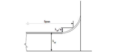
Figure 1.8.3 Effective Bending Span for Local Support Members with Continuous Face Plate along Bracket Edge
8.4 Effective shear span of local support members
8.4.1 The effective shear span, l shr, of a stiffener is defined for typical arrangements in Pt 10, Ch 1, 8.4 Effective shear span of local support members 8.4.5 to Pt 10, Ch 1, 8.4 Effective shear span of local support members 8.4.7 Effective shear span for other arrangements will be specially considered.
8.4.2 The effective shear span may be reduced due to the presence of brackets provided the brackets are effectively supported by the adjacent structure, otherwise the effective shear span is to be as the full length as given in Pt 10, Ch 1, 8.4 Effective shear span of local support members 8.4.4.
8.4.3 The effective shear span may be reduced for brackets fitted on either the flange or the free edge of the stiffener, or for brackets fitted to the attached plating on the side opposite to that of the stiffener. If brackets are fitted at both the flange or free edge of the stiffener, and to the attached plating on the side opposite to that of the stiffener the effective shear span may be calculated using the longer effective bracket arm.
8.4.4 The effective shear span may be reduced by a minimum of s/4000 m at each end of the member, regardless of support detail, hence the effective shear span, l shr, is not to be taken greater than:

Where:
8.4.5 The effective shear span, l shr, for stiffeners forming part of a double skin arrangement is to be taken as shown in Pt 10, Ch 1, 8.4 Effective shear span of local support members 8.4.8.
8.4.6 The effective shear span, l shr, for stiffeners forming part of a single skin arrangement is to be taken as shown in Pt 10, Ch 1, 8.4 Effective shear span of local support members 8.4.8.
8.4.7 Where the face plate of the stiffener is continuous along the curved edge of the bracket, the effective shear span is to be taken as shown in Pt 10, Ch 1, 8.4 Effective shear span of local support members 8.4.8.
8.4.8 For curved and/or long brackets (length/height ratio) the effective bracket length is to be taken as the maximum inscribed 1:1.5 bracket as shown in Pt 10, Ch 1, 8.4 Effective shear span of local support members 8.4.8 (c) and Pt 10, Ch 1, 8.4 Effective shear span of local support members 8.4.8 (c).
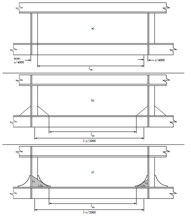
Figure 1.8.4 Effective Shear Span of Stiffeners Supported by Web Stiffeners (Double Skin Construction)
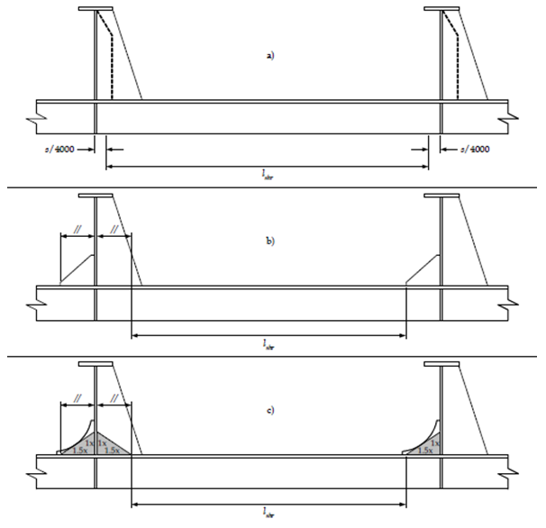
Figure 1.8.5 Effective Shear Span of Stiffeners Supported by Web Stiffeners (Single Skin Construction)
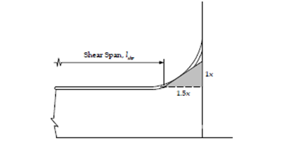
Figure 1.8.6 Effective Shear Span for Local Support Members with Continuous Face Plate along Bracket Edge
8.5 Effective shear span
8.5.1 The effective shear span of a stiffener may be reduced due to the presence of brackets, provided the brackets are effectively supported by the adjacent structure, otherwise the effective shear span is to be as the full length, as given in Pt 10, Ch 1, 8.5 Effective shear span 8.5.3.
8.5.2 The effective shear span may be reduced for brackets fitted on either the flange or the free edge of the stiffener, or for brackets fitted to the attached plating on the side opposite to that of the stiffener. If brackets are fitted at both the flange or free edge of the stiffener, and to the attached plating on the side opposite to that of the stiffener, the effective shear span may be calculated using the longer effective bracket arm.
8.5.3 The effective shear span may be reduced by a minimum of s/4000 m at each end of the member, regardless of support detail, hence the effective shear span is not to be taken greater than:

where
8.6 Effective elastic sectional properties of local support members
8.6.1 The net elastic shear area of local support members is to be taken as:

where


8.6.2 effective shear depth of stiffeners is to be taken as:
 mm
mm
where
 are defined in
Pt 10, Ch 1, 8.6 Effective elastic sectional properties of local support members 8.6.1.
are defined in
Pt 10, Ch 1, 8.6 Effective elastic sectional properties of local support members 8.6.1.
8.6.3 The elastic net section modulus of local support members is to be taken as:
 cm3
cm3
where
| Zel–ϕ–net | = | net section modulus of corresponding upright stiffener, i.e. when ϕw is equal to 90°, in cm3 |
ϕw is defined in Pt 10, Ch 1, 8.6 Effective elastic sectional properties of local support members 8.6.1.
8.7 Effective plastic section modulus and shear area of stiffeners
8.7.1 The net plastic shear area of local support members is to be taken as:

where
hstf , tp-net , ϕw are defined in Pt 10, Ch 1, 8.4 Effective shear span of local support members 8.4.1
8.7.2 The effective net plastic section modulus of local support members is to be taken as:

where
- the stiffener is continuous at the support;
- the stiffener passes through the support plate while it is connected at its termination point by a carling (or equivalent) to adjacent stiffeners;
- the stiffener is attached to an abutting stiffener effective in bending (not a buckling stiffener) or bracket. The bracket is assumed to be bending effective when it is attached to another stiffener (not a buckling stiffener).

|
= | depth of stiffener web, in mm: |
| = |  for T, L (rolled and built-up) and L2 profiles for T, L (rolled and built-up) and L2 profiles
|
|
| = |  for flat bar and L3 profiles to be taken as given in
Pt 10, Ch 1, 8.7 Effective plastic section modulus and shear area of stiffeners 8.7.2 and
Pt 10, Ch 1, 8.7 Effective plastic section modulus and shear area of stiffeners 8.7.2 for bulb profiles for flat bar and L3 profiles to be taken as given in
Pt 10, Ch 1, 8.7 Effective plastic section modulus and shear area of stiffeners 8.7.2 and
Pt 10, Ch 1, 8.7 Effective plastic section modulus and shear area of stiffeners 8.7.2 for bulb profiles
|
|
| = | hstf for flat bar and L3 profiles to be taken as given in Pt 10, Ch 1, 8.7 Effective plastic section modulus and shear area of stiffeners 8.7.2 and Pt 10, Ch 1, 8.7 Effective plastic section modulus and shear area of stiffeners 8.7.2 for bulb profiles |


but not to be taken greater than 0,5 for L (rolled and built-up) profiles without a mid span tripping bracket


|
= | breadth of flange, in mm. For bulb profiles, see Pt 10, Ch 1, 8.7 Effective plastic section modulus and shear area of stiffeners 8.7.2 and Pt 10, Ch 1, 8.7 Effective plastic section modulus and shear area of stiffeners 8.7.2 |

|
= | distance from mid thickness of stiffener web to the centre of the flange area: |
| = | 0,5 ( ) for rolled angle profiles ) for rolled angle profiles
|
|
| = | 0 for T profiles |
as given in Pt 10, Ch 1, 8.7 Effective plastic section modulus and shear area of stiffeners 8.7.2 and Pt 10, Ch 1, 8.7 Effective plastic section modulus and shear area of stiffeners 8.7.2 for bulb profiles

|
= | height of stiffener measured to the mid thickness of the flange: |
| = |  for profiles with flange of rectangular shape except for L3 profiles for profiles with flange of rectangular shape except for L3 profiles
|
|
| = |  for L3 profiles as given in
Pt 10, Ch 1, 8.7 Effective plastic section modulus and shear area of stiffeners 8.7.2 and
Pt 10, Ch 1, 8.7 Effective plastic section modulus and shear area of stiffeners 8.7.2 for bulb profiles for L3 profiles as given in
Pt 10, Ch 1, 8.7 Effective plastic section modulus and shear area of stiffeners 8.7.2 and
Pt 10, Ch 1, 8.7 Effective plastic section modulus and shear area of stiffeners 8.7.2 for bulb profiles
|


|
= | length of stiffener flange between supporting webs, in metres, but reduced by the arm length of end bracket(s) for stiffeners with end bracket(s) fitted |

|
= | net flange thickness, in mm |
| = | 0 for flat bar stiffeners as given in Pt 10, Ch 1, 8.7 Effective plastic section modulus and shear area of stiffeners 8.7.2 and Pt 10, Ch 1, 8.7 Effective plastic section modulus and shear area of stiffeners 8.7.2 for bulb profiles |
 are defined in
Pt 10, Ch 1, 8.4 Effective shear span of local support members 8.4.1.
are defined in
Pt 10, Ch 1, 8.4 Effective shear span of local support members 8.4.1.
Table 1.8.1 Characteristic flange data for HP bulb profiles
 (mm) |
 (mm) |
 (mm) |
 (mm) |
 (mm) |
 (mm) |
| 200 | 171 | 40 | 14,4 | 10,9 | 188 |
| 220 | 188 | 44 | 16,2 | 12,1 | 206 |
| 240 | 205 | 49 | 17,7 | 13,3 | 225 |
| 260 | 221 | 53 | 19,5 | 14,5 | 244 |
| 280 | 238 | 57 | 21,3 | 15,8 | 263 |
| 300 | 255 | 62 | 22,8 | 16,9 | 281 |
| 320 | 271 | 65 | 25,0 | 18,1 | 300 |
| 340 | 288 | 70 | 26,4 | 19,3 | 318 |
| 370 | 313 | 77 | 28,8 | 21,1 | 346 |
| 400 | 338 | 83 | 31,5 | 22,0 | 374 |
| 430 | 363 | 90 | 33,9 | 24,7 | 402 |
| NOTE | |||||
| Characteristic flange data converted to net scantlings are given as: | |||||

|
|||||

|
|||||

|
|||||
| see Fig. 1.8.1 | |||||
Table 1.8.2 Characteristic flange data for JIS bulb profiles
 (mm) |
 (mm) |
 (mm) |
 (mm) |
 (mm) |
 (mm) |
| 180 | 156 | 34 | 11,9 | 9,0 | 170 |
| 200 | 172 | 39 | 13,7 | 10,4 | 188 |
| 230 | 198 | 45 | 15,2 | 11,7 | 217 |
| 250 | 215 | 49 | 17,1 | 12,9 | 235 |
| NOTE | |||||
| Characteristic flange data converted to net scantlings are as given in Pt 10, Ch 1, 8.7 Effective plastic section modulus and shear area of stiffeners 8.7.2 | |||||
| see Fig. 1.8.1 | |||||

Figure 1.8.7 Characteristic data for bulb profiles
| Copyright 2016 Clasification Society, International Maritime Organization, International Labour Organization or Maritime and Coastguard Agency. All rights reserved. Clasification Society, its affiliates and subsidiaries and their respective officers, employees or agents are, individually and collectively, referred to in this clause as 'Clasification Society'. Clasification Society Register assumes no responsibility and shall not be liable to any person for any loss, damage or expense caused by reliance on the information or advice in this document or howsoever provided, unless that person has signed a contract with the relevant Clasification Society entity for the provision of this information or advice and in that case any responsibility or liability is exclusively on the terms and conditions set out in that contract. |  |