9.1 A parametric series of 96 designs were evaluated
in order to assist in establishing the maximum permissible outflow
values. Nine ship sizes were considered, ranging from 5,000 to 460,000
tons deadweight. For each size, a series of designs were evaluated
covering variations in cargo tank arrangement, and wing tank and double
bottom clearances. Outflow calculations assume the nominal double
bottom and wing tank clearances are maintained through the cargo block.
When calculating the probabilities of breaching cargo tanks, a simplified
prismatic hull shape is assumed.
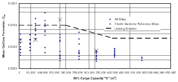
9.2 The mean outflow parameters are displayed
as a function of the cargo capacity in figure
15. In table 1, designs
are sorted by mean outflow parameter. The cargo tank arrangement and
nominal double hull dimensions are also listed in table 1. For example,
"5x2 1x1.1", refers to a design with cargo tanks arranged two wide
and five long; with a 1.0 m wing tank width, and a 1.1 m double bottom
height. The simplified approach was also evaluated on a series of
actual tankers (refer to part A, section
6.4 of these Explanatory Notes for details).
Graph: Mean Outflow Parameters for Series of Tankers
Mean Outflow Parameters for Series
of Tankers
5,000 MT
C=5,849 m3
|
40,000 MT
46,784 m3
|
60,000 MT
70,175 m3
|
95,000 MT
111,111 m3
|
150,000 MT
175,439 m3
|
220,000 MT
257,310 m3
|
283,000 MT
330,994 m3
|
350,000 MT
409,357 m3
|
450,000 MT
526,316 m3
|
Standard
0.015
|
Standard
0.015
|
Standard
0.015
|
5x2 2x2
0.017
|
5x2
2x2.32
0.018
|
6x2
2.5x2.5
0.015
|
Standard
0.013
|
Standard
0.012
|
Standard
0.012
|
5x2
1x1.1
0.013
|
5x2 2x2
0.013
|
5x2 2x2
0.014
|
5x2
2.25x2.25
0.015
|
6x2
2x2.32
0.016
|
Standard
0.014
|
5x5 3x3
0.009
|
5x4 3x3
0.009
|
5x4 3x3
0.010
|
6x2 1x1.1
0.012
|
5x2
2.25x2.25
0.012
|
5x2
2.25x2.25
0.013
|
Standard
0.015
|
5x2
2.5x2.5
0.015
|
7x2
2.5x2.5
0.013
|
5x4 3x3
0.009
|
5x5 3x3
0.009
|
5x5 3x3
0.009
|
5x2
1.25x1.25
0.011
|
6x2 2x2
0.012
|
6x2 2x2
0.012
|
6x2 2x2
0.015
|
Standard
0.015
|
6x2 3x3
0.013
|
5x5 4x2
0.009
|
5x3 3x3
0.009
|
5x3 3x3
0.009
|
7x2
1x1.1
0.011
|
5x2
2.5x2.5
0.011
|
5x2
2.5x2.5
0.012
|
5x2
2.5x2.5
0.014
|
7x2
2x2.32
0.015
|
7x2 3x3
0.012
|
5x3 3x3
0.009
|
5x5
3.5x3.5
0.009
|
5x5
3.5x3.5
0.009
|
6x2
1.25x1.25
0.010
|
7x2 2x2
0.011
|
7x2 2x2
0.011
|
6x2
2.25x2.25
0.014
|
6x2
2.5x2.5
0.014
|
6x2
3.5x3.5
0.012
|
5x5
3.5x3.5
0.009
|
5x4
3.5x3.5
0.008
|
5x4
3.5x3.5
0.009
|
5x2
1.5x1.5
0.009
|
6x2
2.25x2.25
0.011
|
6x2
2.25x2.25
0.011
|
7x2 2x2
0.014
|
5x2 3x3
0.013
|
7x2
3.5x3.5
0.011
|
5x3 4x2
0.009
|
5x5 4x4
0.008
|
5x5 4x4
0.008
|
7x2
1.25x1.25
0.009
|
7x2
2.25x2.25
0.010
|
6x2
2.5x2.5
0.011
|
6x2
2.5x2.5
0.013
|
7x2
2.5x2.5
0.013
|
5x3
2.5x2.5
0.009
|
5x4 4x2
0.008
|
5x3
3.5x3.5
0.008
|
6x3 3x3
0.008
|
6x2
1.5x1.5
0.009
|
6x2
2.5x2.5
0.010
|
7x2
2.25x2.25
0.011
|
7x2
2.25x2.25
0.013
|
6x2 3x3
0.012
|
6x3
2.5x2.5
0.008
|
5x4
3.5x3.5
0.008
|
6x3 3x3
0.008
|
5x3
3.5x3.5
0.008
|
7x2
1.5x1.5
0.008
|
7x2
2.5x2.5
0.009
|
7x2
2.5x2.5
0.010
|
7x2
2.5x2.5
0.012
|
7x2 3x3
0.011
|
5x3 3x3
0.008
|
5x3
3.5x3.5
0.008
|
5x4 4x4
0.008
|
5x4 4x4
0.008
|
|
|
|
|
|
5x3
2x2.32
0.010
|
5x3
3.5x3.5
0.007
|
6x3 3x3
0.008
|
5x3 4x4
0.007
|
5x3 4x4
0.008
|
|
|
|
|
|
5x3
2.5x2.5
0.009
|
6x3 3x3
0.007
|
6x3 4x2
0.008
|
6x3
3.5x3.5
0.007
|
6x3
3.5x3.5
0.007
|
|
|
|
|
|
5x3 3x3
0.008
|
6x3
3.5x3.5
0.007
|
6x3
3.5x3.5
0.007
|
6x3 4x4
0.007
|
6x3 4x4
0.007
|
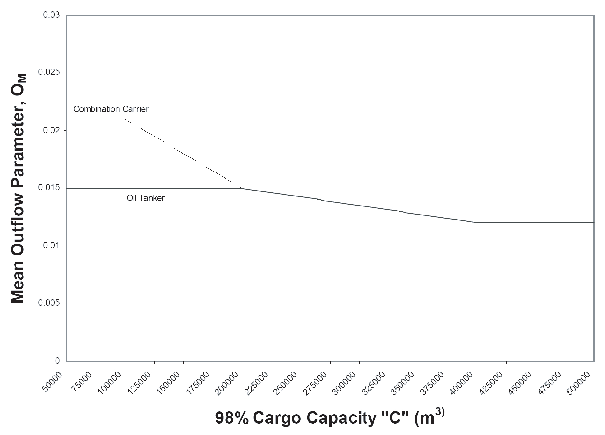
9.3
Figure 16 shows
the maximum permissible mean outflow parameter for oil tankers and
combination carriers of 5,000 metric tons deadweight and above. The
criterion for combination carriers may be applied if calculations
demonstrate that the increased structural strength of the combination
carrier provides outflow equivalency at least equal to a standard
double hull tanker of equal size.
Graph: Mean Outflow Parameter Criterion as per regulation 23, paragraph 3.1