4.0 Methods
                     of Test [7]


                           4.1 General


                               The following tests should be conducted for each type of
                                 nozzle. Before testing, precise drawings of parts and the assembly
                                 should be submitted together with the appropriate specifications (using
                                 SI units). Tests should be carried out at an ambient temperature of
                                 (20,±5)°C, unless other temperatures are indicated.


                           4.2 Visual examination
                           [7.2]


                               Before testing, nozzles should be examined visually with
                                 respect to the following points:


                           4.3 Body strength [7.3]


                                 4.3.1 The design load should be measured on ten
                                 automatic nozzles by securely installing each nozzle at room temperature,
                                 in a tensile/compression test machine and applying a force equivalent
                                 to the application of the rated working pressure.


                               An indicator capable of reading deflection to an accuracy
                                 of 0.01 mm should be used to measure any change in length of the nozzle
                                 between its load bearing points. Movement of the nozzle shank thread
                                 in the threaded bushing of the test machine should be avoided or taken
                                 into account.


                               The hydraulic pressure and load is then released and the
                                 heat responsive element is then removed by a suitable method. When
                                 the nozzle is at room temperature, a second measurement is to be made
                                 using the indicator.


                               An increasing mechanical load to the nozzle is then applied
                                 at a rate not exceeding 500 N/minute, until the indicator reading
                                 at the load bearing point initially measured returns to the initial
                                 value achieved under hydrostatic load. The mechanical load necessary
                                 to achieve this should be recorded as the service load. Calculate
                                 the average service load.


                                 4.3.2 The applied load is then progressively increased
                                 at a rate not exceeding 500 N/minute on each of the five specimens
                                 until twice the average service load has been applied. Maintain this
                                 load for 15 ± 5 s.


                               The load is then removed and any permanent elongation as
                                 defined in 3.6 is recorded.


                           4.4 Leak resistance and
                           hydrostatic strength tests (see 
                              3.8
                              )
                           [7.4]


                                 4.4.1 Twenty nozzles should be subjected to a
                                 water pressure of twice their rated working pressure, but not less
                                 than 34.5 bar. The pressure is increased from 0 bar to the test pressure,
                                 maintained at twice rated working pressure for a period of 3 min and
                                 then decreased to 0 bar. After the pressure has returned to 0 bar,
                                 it is increased to the minimum operating pressure specified by the
                                 manufacturer in not more than 5 s. This pressure is to be maintained
                                 for 15 s and then increased to rated working pressure and maintained
                                 for 15 s.


                                 4.4.2 Following the test of 4.4.1, the twenty nozzles should
                                 be subjected to an internal hydrostatic pressure of four times the
                                 rated working pressure. The pressure is increased from 0 bar to four
                                 times the rated working pressure and held there for a period of 1
                                 minute. The nozzle under test should not rupture, operate or release
                                 any of its operating parts during the pressure increase nor while
                                 being maintained at four times the rated working pressure for 1 minute.


                           4.5 Functional test (see 
                              3.5
                              ) [7.5]


                                 4.5.1 Nozzles having nominal release temperatures
                                 less than 78°C, should be heated to activation in an oven. While
                                 being heated, they should be subjected to each of the water pressures
                                 specified in 4.5.3 applied
                                 to their inlet. The temperature of the oven should be increased to
                                 400 ± 20°C in 3 min measured in close proximity to the
                                 nozzle. Nozzles having nominal release temperatures exceeding 78°C
                                 should be heated using a suitable heat source. Heating should continue
                                 until the nozzle has activated.


                                 4.5.2 Eight nozzles should be tested in each normal
                                 mounting position and at pressures equivalent to the minimum operating
                                 pressure, the rated working pressure and the the average operating
                                 pressure. The flowing pressure should be at least 75% of the initial
                                 operating pressure.


                                 4.5.3 If lodgement occurs in the release mechanism
                                 at any operating pressure and mounting position, 24 more nozzles should
                                 be tested in that mounting position and at that pressure. The total
                                 number of nozzles for which lodgement occurs should not exceed 1 in
                                 the 32 tested at that pressure and mounting position.


                                 4.5.4 Lodgement is considered to have occurred
                                 when one or more of the released parts lodge in the discharge assembly
                                 in such a way a to cause the water distribution to be altered after
                                 the period of time specified in 3.5.1.


                                 4.5.5 In order to check the strength of the deflector/orifice
                                 assembly, three nozzles should be submitted to the functional test
                                 in each normal mounting position at 125 percent of the rated working
                                 pressure. The water should be allowed to flow at 125 percent of the
                                 rated working pressure for a period of 15 min.


                           4.6 Heat responsive element
                           operating characteristics


                                 4.6.1 Operating temperature test (see 
                                    3.3
                                    ) [7.6]


                                     Ten nozzles should be heated from room temperature to 20
                                       to 22°C below their nominal release temperature. The rate of increase
                                       of temperature should not exceed 20°C/min and the temperature
                                       should be maintained for 10 min. The temeprature should then be increased
                                       at a rate between 0.4°C/min to 0.7°C/min until the nozzle
                                       operates.


                                     The nominal operating temperature should be ascertained
                                       with equipment having an accuracy of ±0.35% of the nominal
                                       temperature rating or ±0.25°C, whichever is greater.


                                     The test should be conducted in a water bath for nozzles
                                       or separate glass bulbs having nominal release temperatures less than
                                       or equal to 80°C. A suitable oil should be used for higher-rated
                                       release elements. The liquid bath should be constructed in such a
                                       way that the temperature deviation within the test zone does not exceed
                                       0.5%, or 0.5°C, whichever is greater.


                                 4.6.2 Dynamic heating test (see 
                                    3.4
                                    )


                                       4.6.2.1 Plunge test


                                           Tests should be conducted to determine the standard and
                                             worst case orientations as defined in 1.4 and 1.5. Ten additional
                                             plunge test should be performed at both of the identified orientations.
                                             The worst case orientation should be as defined in 3.14.1. The RTI is calculated as
                                             described in 4.6.2.3 and 4.6.2.4 for
                                             each orientation, respectively. The plunge tests are to be conducted
                                             using a brass nozzle mount designed such that the mount or water temperature
                                             rise does not exceed 2°C for the duration of an individual plunge
                                             test up to a response time of 55 s. (The temperature should be measured
                                             by a thermocouple heatsinked and embedded in the mount not more than
                                             8 mm radially outward from the root diameter of the internal thread
                                             or by a thermocouple located in the water at the centre of the nozzle
                                             inlet.) If the response time is greater than 55 s, then the mount
                                             or water temperature in degrees Celsius should not increase more than
                                             0.036 times the response time in seconds for the duration of an individual
                                             plunge test.


                                           The nozzle under test should have 1 to 1.5 wraps of PTFE
                                             sealant tape applied to the nozzle threads. It should be screwed into
                                             a mount to a torque of 15 ± 3 Nm. Each nozzle is to be mounted
                                             on a tunnel test section cover and maintained in a conditioning chamber
                                             to allow the nozzle and cover to reach ambient temperature for a period
                                             of not less than 30 min.


                                           At least 25 ml of water, conditioned to ambient temperature,
                                             should be introduced into the nozzle inlet prior to testing. A time
                                             accurate to ±0.01 s with suitable measuring devices to sense
                                             the time between when the nozzle is plunged into the tunnel and the
                                             time it operates should be utilized to obtain the response time.


                                           A tunnel should be utilized with air flow and temperature
                                             conditionsfootnote at the test section (nozzle
                                             location) selected from the appropriate range of conditions shown
                                             in table 2. To minimize
                                             radiation exchange between the sensing element and the boundaries
                                             confining the flow, the test section of the apparatus should be designed
                                             to limit radiation effects to within ±3% of calculated RTI
                                             valuesfootnote.


                                             Table 2 Plunge Oven Test
                                                   Conditions


                                                      |  
                                                         
                                                       | 
                                                      Air Temperature ranges 4
                                                         
                                                       | 
                                                      Velocity ranges 5
                                                         
                                                       | 
                                                    
                                                   
                                                      | Normal
                                                         Temperature, ºC
                                                         
                                                       | 
                                                      Standard
                                                         Response, ºC
                                                         
                                                       | 
                                                      Special
                                                         response, ºC
                                                         
                                                       | 
                                                      Fast
                                                         Response, ºC
                                                         
                                                       | 
                                                      Standard
                                                         Response, m/s
                                                         
                                                       | 
                                                      Special
                                                         response, m/s
                                                         
                                                       | 
                                                      Fast Response
                                                         Nozzle, m/s
                                                         
                                                       | 
                                                    
                                                   
                                                      | 57 to
                                                         77
                                                         
                                                       | 
                                                      191 to
                                                         203
                                                         
                                                       | 
                                                      129 to
                                                         141
                                                         
                                                       | 
                                                      129 to
                                                         141
                                                         
                                                       | 
                                                      2.4 to
                                                         2.6
                                                         
                                                       | 
                                                      2.4 to
                                                         2.6
                                                         
                                                       | 
                                                      1.65 to
                                                         1.85
                                                         
                                                       | 
                                                    
                                                   
                                                      | 79 to
                                                         107
                                                         
                                                       | 
                                                      282 to
                                                         300
                                                         
                                                       | 
                                                      191 to
                                                         203
                                                         
                                                       | 
                                                      191 to
                                                         203
                                                         
                                                       | 
                                                      2.4 to
                                                         2.6
                                                         
                                                       | 
                                                      2.4 to
                                                         2.6
                                                         
                                                       | 
                                                      1.65 to
                                                         1.85
                                                         
                                                       | 
                                                    
                                                   
                                                      | 121 to
                                                         149
                                                         
                                                       | 
                                                      382 to
                                                         432
                                                         
                                                       | 
                                                      282 to
                                                         300
                                                         
                                                       | 
                                                      282 to
                                                         300
                                                         
                                                       | 
                                                      2.4 to
                                                         2.6
                                                         
                                                       | 
                                                      2.4 to
                                                         2.6
                                                         
                                                       | 
                                                      1.65 to
                                                         1.85
                                                         
                                                       | 
                                                    
                                                   
                                                      | 163 to
                                                         191
                                                         
                                                       | 
                                                      382 to
                                                         432
                                                         
                                                       | 
                                                      382 to
                                                         432
                                                         
                                                       | 
                                                      382 to
                                                         432
                                                         
                                                       | 
                                                      3.4 to
                                                         3.6
                                                         
                                                       | 
                                                      2.4 to
                                                         2.6
                                                         
                                                       | 
                                                      1.65 to
                                                         1.85
                                                         
                                                       | 
                                                    
                                                   
                                                      | 4.The selected air temperature
                                                         should be known and maintained constant within the test section
                                                         throughout the test section throughout the test to an accuracy of
                                                         +/- 1 ºC for the air temperature range of 129 to 141 ºC within the
                                                         test section and within +/- 2 ºC for all other air
                                                         temperatures.
                                                         
                                                       | 
                                                    
                                                   
                                                      | 5. The selected air velocity
                                                         should be known and maintained constant throughout the test to an
                                                         accuracy of +/-0.03 m/s fpr velocities of 1.65 to 1.85 and 2.4 to
                                                         2.6 m/s and +/-0.04 for velocities 3.4 to 3.6 m/s.
                                                         
                                                       | 


                                           The range of permissible tunnel operating conditions is
                                             shown in table 2. The selected
                                             operating condition should be maintained for the duration of the test
                                             with the tolerances as specified by footnotes 10 and 11 in table 2.


                                       4.6.2.2 Determination of Conductivity Factor (C)
                                       [7.6.2.2]


                                           The conductivity factor (C) should be determined using the
                                             prolonged plunge test (see 4.6.2.2.1) or the prolonged exposure ramp
                                             test (see 4.6.2.2.2).


                                             4.6.2.2.1 Prolonged Plunge Test [7.6.2.2.1]


                                                 The prolonged plunge test is an iterative process to determine
                                                   C and may require up to twenty nozzle samples. A new nozzle sample
                                                   must be used for each test in this section even if the sample does
                                                   not operate during the prolonged plunge test.


                                                 The nozzle under test should have 1 to 1.5 wraps of PTFE
                                                   sealant tape applied to the nozzle threads. It should be screwed into
                                                   a mount to a torque of 15 + 3 Nm. Each nozzle is to be mounted on
                                                   a tunnel test section cover and maintained in a conditioning chamber
                                                   to allow the nozzle and cover to reach ambient temperature for a period
                                                   of not less than 30 min. At least 25 ml of water, conditioned to ambient
                                                   temperature, should be introduced into the nozzle inlet prior to testing.


                                                 A timer accurate to ±0.01 s with suitable measuring
                                                   devices to sense the time between when the nozzle is plunged into
                                                   the tunnel and the time it operates should be utilized to obtain the
                                                   response time.


                                                 The mount temperature should be maintained at 20 ±
                                                   0.5°C for the duration of each test. The air velocity in the tunnel
                                                   test section at the nozzle location should be maintained with ±2%
                                                   of the selected velocity. Air temperature should be selected and maintained
                                                   during the test as specified in table
                                                      3.


                                                   Table 3 Plunge Oven
                                                         Test Conditions for Conductivity Determinations


                                                            | Nominal
                                                               nozzle temperature, ºC
                                                               
                                                             | 
                                                            Oven
                                                               temperature, ºC
                                                               
                                                             | 
                                                            Maximum
                                                               variation of air temperature during test, ºC
                                                               
                                                             | 
                                                          
                                                         
                                                            | 57
                                                               
                                                             | 
                                                            85 to 91
                                                               
                                                             | 
                                                            ± 1.0
                                                               
                                                             | 
                                                          
                                                         
                                                            | 58 to 77
                                                               
                                                             | 
                                                            124 to 130
                                                               
                                                             | 
                                                            ± 1.5
                                                               
                                                             | 
                                                          
                                                         
                                                            | 78 to 107
                                                               
                                                             | 
                                                            193 to 201
                                                               
                                                             | 
                                                            ± 3.0
                                                               
                                                             | 
                                                          
                                                         
                                                            | 121 to 149
                                                               
                                                             | 
                                                            287 to 295
                                                               
                                                             | 
                                                            ± 4.5
                                                               
                                                             | 
                                                          
                                                         
                                                            | 163 to 191
                                                               
                                                             | 
                                                            402 to 412
                                                               
                                                             | 
                                                            ± 6.0
                                                               
                                                             | 


                                                 The range of permissible tunnel operating conditions is
                                                   shown in table 3. The selected
                                                   operating condition should be maintained for the duration of the test
                                                   with the tolerances as specified in table
                                                      3.


                                                 To determine C, the nozzle is immersed in the test stream
                                                   at various air velocities for a maximum of 15 minfootnote. Velocities are chosen such that actuation
                                                   is bracketed between two successive test velocities. That is, two
                                                   velocities must be established such that at the lower velocity (u1)
                                                   actuation does not occur in the 15 min test interval. At the next
                                                   higher velocity (uh), actuation must occur within the 15
                                                   min time limit. If the nozzle does not operate at the highest velocity,
                                                   select an air temperature from table
                                                      3 for the next temperature rating.


                                                 Test velocity selection should insure that:


                                                 The test value of C is the average of the values calculated
                                                   at the two velocities using the following equation:


                                                      where:
                                                      
                                                         | 
                                                                  Δ T
                                                               g
                                                                | 
                                                         = | 
                                                         Actual gas (air) temperature minus the mount temperature (Tm)
                                                               in °C. | 
                                                       
                                                      
                                                         | 
                                                                  Δ T
                                                               ea
                                                                | 
                                                         = | 
                                                         Mean liquid bath operating temperature minus the mount temperature
                                                               (Tm) in °C. | 
                                                       
                                                      
                                                         | 
                                                                  u | 
                                                         = | 
                                                         Actual air velocity
                                                               in the test section in m/s. | 


                                                 The nozzle C value is determined by repeating the bracketing
                                                   procedure three times and calculating the numerical average of the
                                                   three C values. This nozzle C value is used to calculate all standard
                                                   orientation RTI values for determining compliance with 3.14.1.


                                             4.6.2.2.2 Prolonged Exposure Ramp Test [7.6.2.2.2]


                                                 The prolonged exposure ramp test for the determination of
                                                   the parameter C should be carried out in the test section of a wind
                                                   tunnel and with the requirements for the temperature in the nozzle
                                                   mount as described for the dynamic heating test. A preconditioning
                                                   of the nozzle is not necessary.


                                                 Ten samples should be tested of each nozzle type, all nozzles
                                                   positioned in standard orientation. The nozzle should be plunged into
                                                   an air stream of a constant velocity of 1 m/s ± 10% and an
                                                   air temperature at the nominal temperature of the nozzle at the beginning
                                                   of the test.


                                                 The air temperature should then be increased at a rate of
                                                   1 ± 0.25°C/min until the nozzle operates. The air temperature,
                                                   velocity and mount temperature should be controlled from the initiation
                                                   of the rate of rise and should be measured and recorded at nozzle
                                                   operation. The C value is determined using the same equation as in
                                                   4.6.2.2.1 as the average of the ten test values.


                                       4.6.2.3 RTI Value Calculation [7.6.2.3]


                                           The equation used to determine the RTI value is a follows:


                                                where:
                                                
                                                   | 
                                                            
                                                         t
                                                         r
                                                          | 
                                                   = | 
                                                   response
                                                         time of nozzles in seconds | 
                                                 
                                                
                                                   | 
                                                            
                                                         u
                                                          | 
                                                   = | 
                                                   Actual air velocity
                                                         in the test section of the tunnel in m/s from table 2
                                                          | 
                                                 
                                                
                                                   | 
                                                            ΔT
                                                         ea
                                                          | 
                                                   = | 
                                                   Mean
                                                         liquid bath operating temperature of the nozzle minus the ambient
                                                         temperature in °C | 
                                                 
                                                
                                                   | 
                                                            ΔT
                                                         g
                                                          | 
                                                   = | 
                                                   Actual
                                                         air temperature in the test section minus the ambient temperature
                                                         in °C | 
                                                 
                                                
                                                   | 
                                                            C | 
                                                   = | 
                                                   Conductivity factor as determined
                                                         in 4.6.2.2 | 


                                       4.6.2.4 Determination of Worst Case Orientation
                                       RTI


                                           The equation used to determine the RTI for the worst case
                                             orientation is as follows:


                                                where:
                                                
                                                   | 
                                                            
                                                         t
                                                         r-wc
                                                          | 
                                                   = | 
                                                   Response
                                                         time of the nozzles in seconds for the worst case orientation | 


                                           All variables are known at this time per the equation in
                                             paragraph 4.6.2.3 except RTIwc (Response Time Index for
                                             the worst case orientation) which can be solved iteratively per the
                                             above equation.


                                           In the case of fast response nozzles, if a solution for
                                             the worse case orientation RTI is unattainable, plunge testing in
                                             the worst case orientation should be repeated using the plunge test
                                             conditions under Special Response shown in table 2.


                           4.7 Heat Exposure Test
                           [7.7]


                                 4.7.1 Glass Bulb Nozzles (see 
                                    3.9.1
                                    )


                                     Glass bulb nozzles having nominal release temperatures less
                                       than or equal to 80°C should be heated in a water bath from a
                                       temperature of (20 ± 5)°C to (20 ± 2)°C below
                                       their nominal release temperature. The rate of increase of temperature
                                       should not exceed 20°C/min. High temperature oil, such as silicone
                                       oil should be used for higher temperature rated release elements.


                                     This temperature should then be increased at a rate of 1°C/min
                                       to the temperature at which the gas bubble dissolves, or to a temperature
                                       5°C lower than the nominal operating temperature, whichever is
                                       lower. Remove the nozzle from the liquid bath and allow it to cool
                                       in air until the gas bubble has formed again. during the cooling period,
                                       the pointed end of the glass bulb (seal end) should be pointing downwards.
                                       This test should be performed four times on each of four nozzles.


                                 4.7.2 All Uncoated Nozzles (see 
                                    3.9.2
                                    ) [7.7.2]


                                     Twelve uncoated nozzles should be exposed for a period of
                                       90 days to a high ambient temperature that is 11°C below the nominal
                                       rating or at the temperature shown in table 4, whichever is lower, but not less than 49°C. If
                                       the service load is dependent on the service pressure, nozzles should
                                       be tested under the rated working pressure. After exposure, four of
                                       the nozzles should be subjected to the tests specified in 4.4.1, four nozzles to the test
                                       of 4.5.1. two at the minimum
                                       operating pressure and two at the rated working pressure, and four
                                       nozzles to the requirements 3.3.
                                       If a nozzle fails the applicable requirements of a test, eight additional
                                       nozzles should be tested as described above and subjected to the test
                                       in which the failure was recorded. All eight nozzles should comply
                                       with the test requirements.


                                       Table 4 Test Temperatures
                                             for Coated and Uncoated Nozzles


                                                | Values in degrees Celsius
                                                   
                                                 | 
                                              
                                             
                                                | Nominal release
                                                   temperature
                                                   
                                                 | 
                                                Uncoated nozzle
                                                   test temperature
                                                   
                                                 | 
                                                Coated nozzle
                                                   test temperature
                                                   
                                                 | 
                                              
                                             
                                                | 57–60
                                                   
                                                 | 
                                                49
                                                   
                                                 | 
                                                49
                                                   
                                                 | 
                                              
                                             
                                                | 61–77
                                                   
                                                 | 
                                                52
                                                   
                                                 | 
                                                49
                                                   
                                                 | 
                                              
                                             
                                                | 78–107
                                                   
                                                 | 
                                                79
                                                   
                                                 | 
                                                66
                                                   
                                                 | 
                                              
                                             
                                                | 108–149
                                                   
                                                 | 
                                                121
                                                   
                                                 | 
                                                107
                                                   
                                                 | 
                                              
                                             
                                                | 150 to 191
                                                   
                                                 | 
                                                149
                                                   
                                                 | 
                                                149
                                                   
                                                 | 
                                              
                                             
                                                | 192–246
                                                   
                                                 | 
                                                191
                                                   
                                                 | 
                                                191
                                                   
                                                 | 
                                              
                                             
                                                | 247–302
                                                   
                                                 | 
                                                246
                                                   
                                                 | 
                                                246
                                                   
                                                 | 
                                              
                                             
                                                | 303–343
                                                   
                                                 | 
                                                302
                                                   
                                                 | 
                                                302
                                                   
                                                 | 


                                 4.7.3 Coated Nozzles (see 
                                    3.9.3
                                    ) [7.7.3]


                                     In addition to the exposure test of 4.7.2 in an uncoated version, twelve
                                       coated nozzles should be exposed to the test of 4.7.2 using the temperatures
                                       shown in table 4 for coated
                                       nozzles.


                                     The test should be conducted for 90 days. During this period,
                                       the sample should be removed from the oven at intervals of approximately
                                       7 days and allowed to cool for 2 h to 4 h. During this cooling period,
                                       the sample should be examined. After exposure, four of the nozzles
                                       should be subjected to the tests specified in 4.4.1, four nozzles to the test
                                       of 4.5.1; two at the minimum
                                       operating pressure and two at the rated working pressure, and four
                                       nozzles to the requirements of 3.3.


                           4.8 Thermal Shock Test
                           for Glass Bulb Nozzles (see 
                              3.10
                              )
                           [7.8]


                               Before starting the test, condition at least 24 nozzles
                                 at room temperature of 20 to 25°C for at least 30 min.


                               The nozzles should be immersed in a bath of liquid, the
                                 temperature of which should be 10 ± 2°C below the nominal
                                 release temperature of the nozzles. After 5 min, the nozzles are to
                                 be remove from the bath and immersed immediately in another bath of
                                 liquid, with the bulb seal downwards, at a temperature of 10 ±
                                 1°C. Then test the nozzles in accordance with 4.5.1.


                           4.9 Strength Test for
                           Release Elements [7.9]


                                 4.9.1 Glass Bulbs (see 
                                    3.7.1
                                    ) [7.9.1]


                                     At least 15 sample bulbs in the lowest temperature rating
                                       of each bulb type should be positioned individually in a test fixture
                                       using the sprinkler seating parts. Each bulb should then be subjected
                                       to a uniformly increasing force at a rate not exceeding 250 N/s in
                                       the test machine until the bulb fails.


                                     Each test should be conducted with the bulb mounted in new
                                       seating parts. The mounting device may be reinforced externally to
                                       prevent its collapse, but in a manner which does not interfere with
                                       bulb failure.


                                     Record the failure load for each bulb. Calculate the lower
                                       tolerance limit (TL1) for bulb strength. Using the values of service
                                       load recorded in 4.3.1, calculate
                                       the upper tolerance limit (TL2) for the bulb design load. Verify compliance
                                       with 3.7.1.


                                 4.9.2 Fusible Elements (see 
                                    3.7.2
                                    )


                           4.10 Water Flow Test
                           (see 
                              3.4.1
                              ) [7.10]


                               The nozzle and a pressure gauge should be mounted on a supply
                                 pipe. The water flow should be measured at pressures ranging from
                                 the minimum operating pressure to the rated working pressure at intervals
                                 of approximately 10% of the service pressure range on two sample nozzles.
                                 In one series of tests, the pressure should be increased from zero
                                 to each value and, in the next series, the pressure shall be decreased
                                 from the rated pressure to each value. The flow constant, K, should
                                 be averaged from each series of readings, i.e., increasing pressure
                                 and decreasing pressure. During the test, pressures should be corrected
                                 for differences in height between the gauge and the outlet orifice
                                 of the nozzle.


                           4.11 Water Distribution
                           and Droplet Size Tests


                                 4.11.1 Water Distribution (see 
                                    3.4.2
                                    )


                                     The tests should be conducted in a test chamber of minimum
                                       dimensions 7 m x 7 m or 300% of the maximum design area being tested,
                                       whichever is greater. For standard automatic nozzles, install a single
                                       open nozzle and then four open nozzles of the same type arranged in
                                       a square, at maximum spacings specified by the manufacturer, on piping
                                       prepared for this purpose. For pilot type nozzles, install a single
                                       nozzle and then the maximum number of slave nozzles at their maximum
                                       spacings, specified in the Manufacturer Design and Installation Instructions.


                                     The distance between the ceiling and the distribution plate
                                       should be 50 mm for upright nozzles and 275 mm for pendent nozzles.
                                       For nozzles without distribution plates, the distances shall be measured
                                       from the ceiling to the highest nozzle outlet.


                                     Recessed, flush and concealed type nozzles should be mounted
                                       in a false ceiling of dimensions not less than 6 m x 6 m and arranged
                                       symmetrically in the test chamber. The nozzles should be fitted directly
                                       into the horizontal pipework by means of “T" or elbow fittings.


                                     The water discharge distribution in the protected area below
                                       a single nozzle and between the multiple nozzles should be collected
                                       and measured by means of square measuring containers nominally 300
                                       mm on a side. The distance between the nozzles and the upper edge
                                       of the measuring containers should be the maximum specified by the
                                       manufacturer. The measuring containers should be positioned centrally,
                                       beneath the single nozzle and beneath the multiple nozzles.


                                     The nozzles should be discharged both at the minimum operating
                                       and rated working pressures specified by the manufacturer and the
                                       minimum and maximum installation heights specified by the manufacturer.


                                     The water should be collected for at least 10 min to assist
                                       in characterizing nozzle performance.


                                 4.11.2 Water Droplet Size (see 
                                    3.4.3
                                    )


                                     The mean water droplet diameters. velocities, droplet size
                                       distribution, number density and volume flux should be determined
                                       at both the minimum and maximum flow rates specified by the manufacturer.
                                       Once the data is gathered, the method of the “Standard Practice
                                       for Determining Data Criteria and Processing for Liquid Drop Size
                                       Analysis" (ASTM E799-92) will be used to determine the appropriate
                                       sample size, class size widths, characteristic drop sizes and measured
                                       dispersion of the drop size distribution. This data should be taken
                                       at various points within the spray distribution as described in 3.4.3.


                           4.12 Corrosion Test
                           [7.12]


                                 4.12.1 Stress Corrosion
                                 Test for Brass Nozzle Parts (see 
                                    3.11.1
                                    )


                                     Five nozzles should be subjected to the following aqueous
                                       ammonia test. The inlet of each nozzle should be sealed with a nonreactive
                                       cap, e.g., plastic.


                                     The samples are degreased and exposed for 10 days to a moist
                                       ammonia-air mixture in a glass container of volume 0.02 ± 0.01
                                       m3.


                                     An aqueous ammonia solution, having a density of 0.94 g/cm3, should be maintained in the bottom of the container, approximately
                                       40 mm below the bottom of the samples. A volume of aqueous ammonia
                                       solution corresponding to 0.01 ml per cubic centimetre of the volume
                                       of the container will give approximately the following atmospheric
                                       concentrations: 35% ammonia, 5% water vapour, and 60% air. The inlet
                                       of each sample should be sealed with a nonreactive cap, e.g. plastic.


                                     The moist ammonia-air mixture should be maintained as closely
                                       as possible at atmospheric pressure, with the temperature maintained
                                       at 34 ± 2°C. Provision should be made for venting the chamber
                                       via a capillary tube to avoid the build-up of pressure. Specimens
                                       should be shielded from condensate drippage.


                                     After exposure, rinse and dry the nozzles, and conduct a
                                       detailed examination. If a crack, delamination or failure of any operating
                                       part is observed, the nozzle(s) should be subjected to a leak resistance
                                       test at the rated pressure for 1 min and to the functional test at
                                       the minimum flowing pressure (see 3.1.5).


                                     Nozzles showing cracking, delamination or failure of any
                                       non-operating part should not show evidence of separation of permanently
                                       attached parts when subjected to flowing water at the rated working
                                       pressure for 30 min.


                                 4.12.2 Stress-Corrosion
                                 Cracking of Stainless Steel Nozzle Parts (see 
                                    3.11.1
                                    )


                                       4.12.2.1 Five samples are to be degreased prior
                                       to being exposed to the magnesium chloride solution.


                                       4.12.2.2 Parts used in nozzles are to be place
                                       in a 500-millilitre flask that is fitted with a thermometer and a
                                       wet condenser approximately 760 mm long. the flask is to be filled
                                       approximately one-half full with 42% by weight magnesium chloride
                                       solution, placed on a thermostatically-controlled electrically heated
                                       mantel, and maintained at a boiling temperature of 150 ± 1°C.
                                       The parts are to be unassembled, that is, not contained in a nozzle
                                       assembly. The exposure is to last for 500 hours.


                                       4.12.2.3 After exposure period, the test samples
                                       are to be removed from the boiling magnesium chloride solution and
                                       rinsed in deionized water.


                                       4.12.2.4 The test samples are then to be examined
                                       using a microscope having a magnification of 25X for any cracking,
                                       delamination, or other degradation as a result of the test exposure.
                                       Test samples exhibiting degradation are to be tested as described
                                       in 4.12.5.5 or 4.12.5.6,
                                       as applicable. test samples not exhibiting degradation are considered
                                       acceptable without further test.


                                       4.12.2.5 Operating parts exhibiting degradation
                                       are to be further tested as follows. Five new sets of parts are to
                                       be assembled in nozzle frames made of materials that do not alter
                                       the corrosive effects of the magnesium chloride solution on the stainless
                                       steel parts. These test samples are to be degreased and subjected
                                       to the magnesium chloride solution exposure specified in paragraph 4.12.5.2. following the exposure,
                                       the test samples should withstand, without leakage, a hydrostatic
                                       test pressure equal to the rated working pressure for 1 minute and
                                       then be subjected to the functional test at the minimum operating
                                       pressure in accordance with 4.5.1.


                                       4.12.2.6 Non-operating parts exhibiting degradation
                                       are to be further tested as follows. Five new sets of parts are to
                                       be assembled in nozzle frames made of materials that do not alter
                                       the corrosive effects of the magnesium chloride solution on the stainless
                                       steel parts. These test samples are to be degreased and subjected
                                       to the magnesium chloride solution exposure specified in paragraph 4.12.5.1. Following the exposure,
                                       the test samples should withstand a flowing pressure equal to the
                                       rated working pressure for 30 minutes without separation of permanently
                                       attached parts.


                                 4.12.3 Sulphur Dioxide
                                 Corrosion Test (see 
                                    3.11.2
                                     and 
                                    3.14.2
                                    )


                                     Ten nozzles should be subjected to the following sulphur
                                       dioxide corrosion test. The inlet of each sample should be sealed
                                       with a nonreactive cap, e.g. plastic.


                                     The test equipment should consist of a 5 litre vessel (instead
                                       of a 5 litre vessel, other volumes up to 15 litre may be used in which
                                       case the quantities of chemicals given below shall be increased in
                                       proportion) made of heat-resistant glass, with a corrosion-resistant
                                       lid of such a shape as to prevent condensate dripping on the nozzles.
                                       The vessel should be electrically heated through the base, and provided
                                       with a cooling coil around the side walls. A temperature sensor placed
                                       centrally 160 mm ± 20 mm above the bottom of the vessel should
                                       regulate the heating so that the temperature inside the glass vessel
                                       is 45°C ± 3°C. During the test, water should flow through
                                       the cooling coil at a sufficient rate to keep the temperature of the
                                       discharge water below 30°C. This combination of heating and cooling
                                       should encourage condensation on the surfaces of the nozzles. The
                                       sample nozzles should be shielded from condensate drippage.


                                     The nozzles to be tested should be suspended in their normal
                                       mounting position under the lid inside the vessel and subjected to
                                       a corrosive sulphur dioxide atmosphere for 8 days. The corrosive atmosphere
                                       should be obtained by introducing a solution made up by dissolving
                                       20 g of sodium thiosulphate (Na2S2O3H2O) crystals in 500 ml of water.


                                     For at least six days of the 8-day exposure period, 20 ml
                                       of dilute sulphuric acid consisting of 156 ml of normal H2SO4 (0.5 mol/liter) diluted with 844 ml of water should be added
                                       at a constant rate. After 8 days, the nozzles should be removed form
                                       the container and allowed to dry for 4 to 7 days at a temperature
                                       not exceeding 35°C with a relative humidity not greater than 70%.


                                     After the drying period. five nozzles should be subjected
                                       to a functional test at the minimum operating pressure in accordance
                                       with 4.5.1 and five nozzles
                                       should be subjected to the dynamic heating test in accordance with 3.14.2.


                                 4.12.4 Salt Spray
                                 Corrosion Test (see 
                                    3.11.3
                                     and 
                                    3.14.2
                                    ) [7.12.3]


                                       4.12.4.1 Nozzles Intended for Normal Atmospheres


                                           Ten nozzles should be exposed to a salt spray within a fog
                                             chamber. The inlet of each sample should be sealed with a nonreactive
                                             cap, e.g. plastic.


                                           During the corrosive exposure, the inlet thread orifice
                                             is to be sealed by a plastic cap after the nozzles have been filled
                                             with deionized water. The salt solution should be a 20% by mass sodium
                                             chloride solution in distilled water. The pH should be between 6.5
                                             and 3.2 and the density between 1.126 g/ml and 1.157 g/ml when atomized
                                             at 35°C. Suitable means of controlling the atmosphere in the chamber
                                             should be provided. The specimens should be supported in their normal
                                             operating position and exposed to the salt spray (fog) in a chamber
                                             having a volume of at least 0.43 m3 in which the exposure
                                             zone shall be maintained at a temperature of 35 ± 2°C.
                                             The temperature should be recorded at least once per day, at least
                                             7 hours apart (except weekends and holidays when the chamber normally
                                             would not be opened). Salt solution should be supplied from a recirculating
                                             reservoir through air-aspirating nozzles, at a pressure between 0.7
                                             bar (0.07 MPa) and 1.7 bar (0.17 MPa). Salt solution runoff from exposed
                                             samples should be collected and should not return to the reservoir
                                             for recirculation. The sample nozzles should be shielded from condensate
                                             drippage.


                                           Fog should be collected from at least two points in the
                                             exposure zone to determine the rate of application and salt concentration.
                                             The fog should be such that for each 80 cm2 of collection
                                             area, 1 ml to 2 ml of solution should be collected per hour over a
                                             16 hours period and the salt concentration shall be 20 ± 1%
                                             by mass.


                                           The nozzles should withstand exposure to the salt for a
                                             period of 10 days. After this period, the nozzles should be removed
                                             from the fog chamber and allowed to dry for 4 to 7 days at a temperature
                                             of 20 to 25°C in an atmosphere having a relative humidity not
                                             greater than 70%. Following the drying period, five nozzles should
                                             be submitted to the functional test at the minimum operating pressure
                                             in accordance with 4.5.1 and
                                             five nozzles should be subjected to the dynamic heating test in accordance
                                             with 3.14.2.


                                       4.12.4.2 Nozzles Intended for Corrosive Atmospheres
                                       [7.12.3.2]


                                           Five nozzles should be subjected to the tests specified
                                             in 4.12.3.1 except that
                                             the duration of the salt spray exposure shall be extended from 10
                                             days to 30 days.


                                 4.12.5 Moist Air Exposure
                                 Test (see 
                                    3.11.4
                                     and 
                                    3.14.2
                                    ) [7.12.4]


                                     Ten nozzles should be exposed to a high temperature-humidity
                                       atmosphere consisting of a relative humidity of 98% ± 2% and
                                       a temperature of 95°C ± 4°C. The nozzles are to be
                                       installed on a pipe manifold containing deionized water. The entire
                                       manifold is to be placed in the high temperature humidity enclosure
                                       for 90 days. After this period, the nozzles should be removed from
                                       the temperature-humidity enclosure and allowed to dry for 4-7 days
                                       at a temperature of 25 ± 5°C in an atmosphere having a
                                       relative humidity of not greater than 70%. Following the drying period,
                                       five nozzles should be functionally tested at the minimum operating
                                       pressure in accordance with 4.5.1 and
                                       five nozzles should be subjected to the dynamic heating test in accordance
                                       with 3.14.2.


                                     At the manufacturer's option, additional samples may be
                                       furnished for this test to provide early evidence of failure. The
                                       additional samples may be removed from the test chamber at 30-day
                                       intervals for testing.


                           4.13 Nozzle Coating
                           Tests [7.13]


                                 4.13.1 Evaporation Test (see 
                                    3.12.1
                                    ) [7.13.1]


                                     A 50 cm3 sample of wax or bitumen should be placed
                                       in a metal or glass cylindrical container, having a flat bottom, an
                                       internal diameter of 55 mm and an internal height of 35 mm. The container,
                                       without lid, should be placed in an automatically controlled electric,
                                       constant ambient temperature oven with air circulation. The temperature
                                       in the oven should be controlled at 16°C below the nominal release
                                       temperature of the nozzle, but at not less than 50°C. The sample
                                       should be weighed before and after 90 days exposure to determine any
                                       loss of volatile matter; the sample should meet the requirements of
                                       3.12.1. 


                                 4.13.2 Low-Temperature Test (see 
                                    3.12.2
                                    ) [7.13.2]


                                     Five nozzles, coated by normal production methods, whether
                                       with wax, bitumen or a metallic coating, should be subjected to a
                                       temperature of -10°C for a period of 24 hours. On removal from
                                       the low-temperature cabinet, the nozzles should be exposed to normal
                                       ambient temperature for a least 30 min before examination of the coating
                                       to the requirements of 3.12.2.


                           4.14 Heat-Resistance
                           Test (see 
                              3.15
                              ) [7.14]


                               One nozzle body should be heated in an oven at 800°C
                                 for a period of 15 min, with the nozzle in its normal installed position.
                                 The nozzle body should then be removed, holding it by the threaded
                                 inlet, and should be promptly immersed in a water bath at a temperature
                                 of approximately 15°C. It should meet the requirements of 3.15.


                           4.15 Water-Hammer Test
                           (see 
                              3.13
                              ) [7.15]


                               Five nozzles should be connected, in their normal operating
                                 position, to the test equipment. After purging the air from the nozzles
                                 and the test equipment, 3,000 cycles of pressure varying from 4 ±
                                 2 bar ((0.4 ± 0.2)MPa) to twice the rated working pressure
                                 should be generated. The pressure should be raised from 4 bar to twice
                                 the rated working pressure at a rate of 60 ± 10 bar/s. At least
                                 30 cycles of pressure per minute should be generated. The pressure
                                 should be measured with an electrical pressure transducer.


                               Visually examine each nozzle for leakage during the test.
                                 After the test, each nozzle should meet the leakage resistance requirement
                                 of 3.8.1 and the functional
                                 requirements of 3.5.1 at the
                                 minimum operating pressure.


                           4.16 Vibration Test
                           (see 
                              3.16
                              ) [7.16]


                                 4.16.1 Five nozzles should be fixed vertically
                                 to a vibration table. They should be subjected at room temperature
                                 to sinusoidal vibrations. The direction of vibration should be along
                                 the axis of the connecting thread.


                                 4.16.2 The nozzles should be vibrated continuously
                                 from 5 Hz to 40 Hz at a maximum rate of 5 min/octave and an amplitude
                                 of 1 mm (1/2 peak-to-peak value). If one or more resonant points are
                                 detected, the nozzles after coming to 40 Hz, should be vibrated at
                                 each of these resonant frequencies for 120 hours/number of resonances.
                                 If no resonances are detected, the vibration from 5 Hz to 40 Hz should
                                 be continued for 120 hours.


                                 4.16.3 The nozzle should then be subjected to
                                 the leakage test in accordance with 3.8.1 and the functional test in accordance with 3.5.1 at the minimum operating pressure.


                           4.17 Impact Test (see 
                              3.17
                              ) [7.17]


                               Five nozzles should be tested by dropping a mass onto the
                                 nozzle along the axial centreline of waterway. The kinetic energy
                                 of the dropped mass at the point of impact should be equivalent to
                                 a mass equal to that of the test nozzle dropped from a height 1 m.
                                 See Figure 2. The mass is
                                 to be prevented from impacting more than once upon each sample.


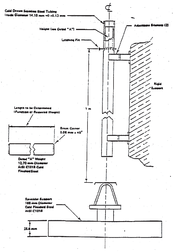
                                 Figure 2 Impact Test Apparatus 


                               Following the test a visual examination of each nozzle shall
                                 show no signs of fracture, deformation, or other deficiency. If none
                                 is detected, the nozzles should be subjected top the leak resistance
                                 test, described in 4.4.1.
                                 Following the leakage test, each sample should meet the functional
                                 test requirement of 4.5.1 at
                                 a pressure equal to the minimum flowing pressure.


                           4.18 Lateral Discharge
                           Test (see 
                              3.18
                              ) [7.19]


                               Water is to be discharged from a spray nozzle at the minimum
                                 operating and rated working pressure. A second automatic nozzle located
                                 at the minimum distance specified by the manufacturer is mounted on
                                 a pipe parallel to the pipe discharging water.


                               The nozzle orifices or distribution plates (if used), are
                                 to be placed 550 mm, 356 mm and 152 mm below a flat smooth ceiling
                                 for three separate tests, respectively at each test pressure. The
                                 top of a square pan measuring 305 mm square and 102 mm deep is to
                                 be positioned 152 mm below the heat responsive element for each test.
                                 The pan is filled with 0.47 litres of heptane. After ignition the
                                 automatic nozzle is to operate before the heptane is consumed.


                           4.19 30 Day Leakage
                           Test (see 
                              3.19
                              ) [7.20]


                               Five nozzles are to be installed on a water filled test
                                 line maintained under a constant pressure of twice the rated working
                                 pressure for 30 days at an ambient temperature of (20 ± 5°C).


                               The nozzles should be inspected visually at least weekly
                                 for leakage. Following completion of this 30 day test, all samples
                                 should meet the leak resistance requirements specified in 3.2.4  and should exhibit no evidence
                                 of distortion or other mechanical damage.


                           4.20 Vacuum Test (see 
                              3.20
                              ) [7.21]


                               Three nozzles should be subjected to a vacuum of 460 mm
                                 of mercury applied to a nozzle inlet for 1 min at an ambient temperature
                                 of (20 ± 5°C). Following this test, each sample should
                                 be examined to verify that no distortion or mechanical damage has
                                 occurred and then should meet the leak resistance requirements specified
                                 in 4.4.1.


                           4.21 Clogging Test (see 
                              3.22
                              ) [7.28]


                                 4.21.1 The water flow rate of an open water mist
                                 nozzle with its strainer or filter should be measured at its rated
                                 working pressure. The nozzle and strainer or filter should then be
                                 installed in test apparatus described in Figure 3 and subjected to 30 minutes
                                 of continuous flow at rated working pressure using contaminated water
                                 which has been prepared in accordance with 4.21.3.


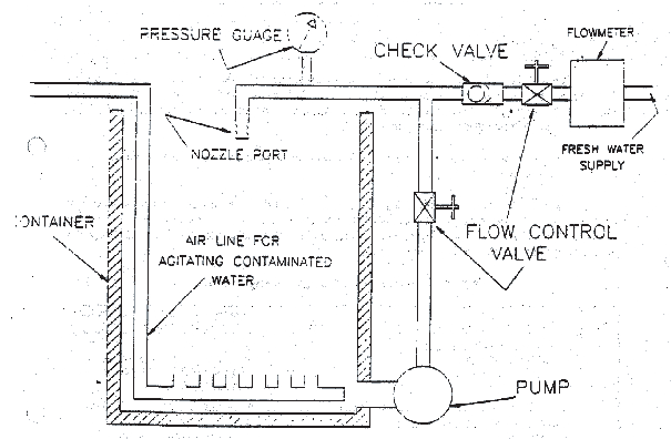
                                  Figure 3 Clogging test apparatus 


                                 4.21.2 Immediately following the 30 minutes of
                                 continuous flow with contaminated water, the flow rate of the nozzle
                                 and strainer or filter should be measured at rated working pressure.
                                 No removal, cleaning or flushing of the nozzle, filter or strainer
                                 is permitted during the test.


                                 4.21.3 The water used during the 30 minutes of
                                 continuous flow at rated working pressure specified in 4.21.1 should
                                 consist of 60 litres of tap water into which has been mixed 1.58 kilograms
                                 of contaminants which sieve as described in table 6. The solution should be
                                 continuously agitated during the test.


                                 Table 6 Contaminant for the
                                       Contaminated Water Cycling Test


                                          | SIEVE DESIGNATION
                                             *
                                             
                                           | 
                                          NOMINAL SIEVE OPENING,
                                             MM
                                             
                                           | 
                                          GRAMS OF CONTAMINANT (± 5
                                             PERCENT)
                                             
                                           | 
                                        
                                       
                                          | PIPE
                                             SCALE
                                             
                                           | 
                                          TOP SOIL
                                             
                                           | 
                                          SAND
                                             
                                           | 
                                        
                                       
                                          | No.
                                             25
                                             
                                           | 
                                          0.706
                                             
                                           | 
                                          —
                                             
                                           | 
                                          456
                                             
                                           | 
                                          200
                                             
                                           | 
                                        
                                       
                                          | No.
                                             50
                                             
                                           | 
                                          0.297
                                             
                                           | 
                                          82
                                             
                                           | 
                                          82
                                             
                                           | 
                                          327
                                             
                                           | 
                                        
                                       
                                          | No.
                                             100
                                             
                                           | 
                                          0.150
                                             
                                           | 
                                          84
                                             
                                           | 
                                          6
                                             
                                           | 
                                          89
                                             
                                           | 
                                        
                                       
                                          | No.
                                             200
                                             
                                           | 
                                          0.074
                                             
                                           | 
                                          81
                                             
                                           | 
                                          —
                                             
                                           | 
                                          21
                                             
                                           | 
                                        
                                       
                                          | No.
                                             325
                                             
                                           | 
                                          0.043
                                             
                                           | 
                                          153
                                             
                                           | 
                                          —
                                             
                                           | 
                                          3
                                             
                                           | 
                                        
                                       
                                          |  
                                             
                                           | 
                                          TOTAL
                                             
                                           | 
                                          400
                                             
                                           | 
                                          544
                                             
                                           | 
                                          640
                                             
                                           | 


             |