2 Passenger Ships
Clasification Society 2024 - Version 9.40
Statutory Documents - IMO Publications and Documents - International Codes - FSS Code - Fire Safety Systems – Resolution MSC.98(73) - Annex - International Code For Fire Safety Systems - Chapter 13 - Arrangement of Means of Escape - 2 Passenger Ships

2 Passenger Ships

2.1 Width of stairways

2.1.1 Basic requirements for stairway widths

 Stairways shall not be less than 900 mm in clear width. The minimum clear width of stairways shall be increased by 10 mm for every one person provided for in excess of 90 persons. The total number of persons to be evacuated by such stairways shall be assumed to be two thirds of the crew and the total number of passengers in the areas served by such stairways. The width of the stairways shall not be inferior to those determined by paragraph 2.1.2.

2.1.2 Calculation method of stairway widths

  2.1.2.1 Basic principles of the calculation

  2.1.2.1.1 This calculation method determines the minimum stairway width at each deck level, taking into account the consecutive stairways leading into the stairway under consideration.

  2.1.2.1.2 It is the intention that the calculation method shall consider evacuation from enclosed spaces within each main vertical zone individually and take into account all of the persons using the stairway enclosures in each zone, even if they enter that stairway from another vertical zone.

  2.1.2.1.3 For each main vertical zone the calculation shall be completed for the night time (case 1) and day time (case 2) and the largest dimension from either case used for determining the stairway width for each deck under consideration.

  2.1.2.1.4 The calculation of stairway widths shall be based upon the crew and passenger load on each deck. Occupant loads shall be rated by the designer for passenger and crew accommodation spaces, service spaces, control spaces and machinery spaces. For the purpose of the calculation the maximum capacity of a public space shall be defined by either of the following two values: the number of seats or similar arrangements, or the number obtained by assigning 2 m2 of gross deck surface area to each person.

  2.1.2.2 Calculation method for minimum value

  2.1.2.2.1 Basic formulae

 In considering the design of stairway widths for each individual case which allow for the timely flow of persons evacuating to the assembly stations from adjacent decks above and below, the following calculation methods shall be used (see figures 1 and 2):

when joining two decks: W = (N1 + N2) x 10 mm;
when joining three decks: W = (N1 + N2 + 0.5N3) x 10 mm;
when joining four decks: W = (N1 + N2 + 0.5N3 + 0.25N4) x 10 mm; and
when joining five decks or more decks, the width of the stairways shall be determined by applying the above formula for four decks to the deck under consideration and to the consecutive deck,
where:    
W = the required tread width between handrails of the stairway.
The calculated value of W may be reduced where available landing area S is provided in stairways at the deck level defined by subtracting P from Z, such that:
P = S x 3.0 persons/m2; and Pmax = 0.25Z
where:    
Z = the total number of persons expected to be evacuated on the deck being considered
P = the number of persons taking temporary refuge on the stairway landing, which may be subtracted from Z to a maximum value of P = 0.25Z (to be rounded down to the nearest whole number)
S = the surface area (m 2 ) of the landing, minus the surface area necessary for the opening of doors and minus the surface area necessary for accessing the flow on stairs (see figure 1)
N = the total number of persons expected to use the stairway from each consecutive deck under consideration; N1 is for the deck with the largest number of persons using that stairway; N2 is taken for the deck with the next highest number of persons directly entering the stairway flow such that, when sizing the stairway width as each deck level, N1 > N2 > N3 > N4 (see figure 2). These decks are assumed to be on or upstream (i.e. away from the embarkation deck) of the deck being considered.

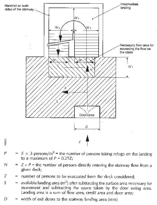
Figure 1 Landing Calculation for Stairway Width Reduction

Figure 2 Minimum Stairway Width (W) Calculation Example

  2.1.2.2.2 Distribution of persons

  2.1.2.2.2.1 The dimension of the means of escape shall be calculated on the basis of the total number of persons expected to escape by the stairway and through doorways, corridors and landings (see figure 3). Calculations shall be made separately for the two cases of occupancy of the spaces specified below. For each component part of the escape route, the dimension taken shall not be less than the largest dimension determined for each case:

Case 1: Passengers in cabins with maximum berthing capacity fully occupied; members of the crew in cabins occupied to 2/3 of maximum berthing capacity; and service spaces occupied by 1/3 of the crew.
Case 2: Passengers in public spaces occupied to 3/4 of maximum capacity, 1/3 of the crew distributed in public spaces; service spaces occupied by 1/3 of the crew; and crew accommodation occupied by 1/3 of the crew.

Figure 3 Occupant Loading Calculation

  2.1.2.2.2.2 The maximum number of persons contained in a vertical zone, including persons entering stairways from another main vertical zone, shall not be assumed to be higher than the maximum number of persons authorized to be carried on board for the calculation of stairway widths only.

2.1.3 Prohibition of decrease in width in the direction to the assembly station footnote

 The stairway shall not decrease in width in the direction of evacuation to the assembly station. Where several assembly stations are in one main vertical zone, the stairway width shall not decrease in the direction of the evacuation to the most distant assembly station.

2.2 Details of stairways

  2.2.1 Handrails

Stairways shall be fitted with handrails on each side. The maximum clear width between handrails shall be 1,800 mm.

  2.2.2 Alignment of stairways

All stairways sized for more than 90 persons shall be aligned fore and aft.

  2.2.3 Vertical rise and inclination

Stairways shall not exceed 3.5 m in vertical rise without the provision of a landing and shall not have an angle of inclination greater than 45°.

  2.2.4 Landings

With the exception of intermediate landings, landings at each deck level shall be not less than 2 m2 in area and shall increase by 1 m2 for every 10 persons provided for in excess of 20 persons, but need not exceed 16 m2, except for those landings servicing public spaces having direct access onto the stairway enclosure. Intermediate landings shall be sized in accordance with paragraph 2.3.1.

2.3 Doorways and corridors

  2.3.1 Doorways and corridors and intermediate landings included in means of escape shall be sized in the same manner as stairways.

  2.3.2 The aggregate width of stairway exit doors to the assembly station shall not be less than the aggregate width of stairways serving this deck.

2.4 Evacuation routes to the embarkation deck

  2.4.1 Assembly station

It shall be recognized that the evacuation routes to the embarkation deck may include an assembly station. In this case, consideration shall be given to the fire-protection requirements and sizing of corridors and doors from the stairway enclosure to the assembly station and from the assembly station to the embarkation deck, noting that evacuation of persons from assembly stations to embarkation positions will be carried out in small control groups.

  2.4.2 Routes from the assembly station to the survival craft embarkation position

Where the passengers and crew are held at an assembly station which is not at the survival craft embarkation position, the dimension of stairway width and doors from the assembly station to this position shall be based on the number of persons in the controlled group. The width of these stairways and doors need not exceed 1,500 mm unless larger dimensions are required for evacuation of these spaces under normal conditions.

2.5 Means of escape plans

  2.5.1 Means of escape plans shall be provided indicating the following:

  • .1 the number of the crew and passengers in all normally occupied spaces;

  • .2 the number of crew and passengers expected to escape by stairway and through doorways, corridors and landings;

  • .3 assembly stations and survival craft embarkation positions;

  • .4 primary and secondary means of escape; and

  • .5 width of stairways, doors, corridors and landing areas.

  2.5.2 Means of escape plans shall be accompanied by detailed calculations for determining the width of escape stairways, doors, corridors and landing areas.


Copyright 2022 Clasifications Register Group Limited, International Maritime Organization, International Labour Organization or Maritime and Coastguard Agency. All rights reserved. Clasifications Register Group Limited, its affiliates and subsidiaries and their respective officers, employees or agents are, individually and collectively, referred to in this clause as 'Clasifications Register'. Clasifications Register assumes no responsibility and shall not be liable to any person for any loss, damage or expense caused by reliance on the information or advice in this document or howsoever provided, unless that person has signed a contract with the relevant Clasifications Register entity for the provision of this information or advice and in that case any responsibility or liability is exclusively on the terms and conditions set out in that contract.