1.5.1 Scope
This procedure details the laboratory determination of transportable
moisture limit (TML) for coals up to a nominal top size of 50 mm. The procedure is based
on a modification of the Proctor/Fagerberg test described in section 1.3 of this
appendix.
Key modifications to the original test procedure contained in 1.3 of this
appendix are:
-
.1 Sample preparation to facilitate the testing of 0 x 50 mm coal
through reconstitution to -25 mm;
-
.2 Use of a 150 mm diameter compaction cylinder; and
-
.3 Sample compaction using a hammer equivalent to the
Proctor/Fagerberg "D" energy hammer.
The transportable moisture limit is the moisture content corresponding to
the intersection of the 70% degree saturation curve and the test sample compaction
curve.
In the case of coals where moisture freely drains from the sample such that
the test sample compaction curve does not extend to or beyond 70% saturation, the test
is taken to indicate a cargo where water passes through the spaces between particles and
there is no increase in pore water pressure. Therefore, the cargo is not liable to
liquefy. (See 7.2.2 of this Code).
The procedure commences with a drum of coal containing a sample of not less
than 170 kg delivered to the testing laboratory and terminates with the laboratory
reporting the test result for the coal. Details of the sample collection process are
excluded from this procedure. However, it is important that the sample accurately
represents the size distribution of the cargo and reference should be made to the
normative reference list below.
1.5.2 Normative references
The following documents are referenced in this procedure. For dated
references, only the cited edition applies. For undated references, the latest edition
of the referenced document (including any amendments) applies.
-
– AS 1289.3.5.1:2006, Methods of testing soils for engineering
purposes. Method 3.5.1: Soil classification tests – Determination of the soil
particle density of a soil – Standard method;
-
– ISO 589:2008, Hard Coal – Determination of total moisture;
-
– ISO 3310-2:2013, Test requirements and testing – Part 2: Test
sieves of perforated metal plate; and
-
– ISO 13909-4:2001, Hard coal and coke – Mechanical sampling –
Part 4 – Coal – Preparation of test samples.
1.5.3 Definitions
1.5.3.1 Transportable moisture limit (TML)
The transportable moisture limit (TML) of a cargo which may liquefy means
the maximum moisture content of the cargo which is considered safe for carriage in a
ship not complying with the requirements in 7.3.2 of this Code.
1.5.3.2 Test outcomes
The transportable moisture limit determined by this procedure is the
moisture content corresponding to the intersection of the 70% degree saturation curve
and the test sample compaction curve. This is also referred to as the PFD70 value
(Proctor/Fagerberg – D energy hammer – 70% saturation).
Where moisture freely drains from the sample or the cylindrical mould at
moisture content such that the test sample compaction curve does not extend to or beyond
70% saturation (as described in 1.5.5.3.4), the test is taken to indicate a cargo where
water passes through the spaces between particles and there is no increase in pore water
pressure. Therefore, the cargo is not liable to liquefy. (See 7.2.2 of this Code).
1.5.3.3 Optimum moisture content (OMC)
The optimum moisture content is the moisture content corresponding to the
maximum compaction (maximum dry density) under the specified compaction condition.
1.5.3.4 Gross water content or total moisture (W1)
The moisture content of a sample is calculated as the mass of water divided
by the total mass of solids plus water and is referred to as either the gross water
content or the total moisture content. Gross water content is to be determined using the
method for determining total moisture defined in the standard ISO 589:2008.
1.5.4 Determination of the TML of blends of two or more coals
In circumstances where a shipper intends to load a cargo consisting of a
blend of two or more coals, the shipper may:
1.5.5 Modified Proctor/Fagerberg test procedure for coal
1.5.5.1 Apparatus
1.5.5.1.1 Work area
The work area should be located where the samples are protected from
excessive temperatures, air currents and humidity variations. All samples should be
stored in suitable sample containers, including plastic sample bags, and the containers
should be sealed.
1.5.5.1.2 Standard sieves
Square aperture laboratory sieves of 16 mm and 25 mm aperture as nominated
in ISO 3310-2:2013 are required for reconstitution of the sample at 25 mm top size. A
2.36 mm sieve is required for generation of + 2.36 mm and – 2.36 mm fractions for
particle density determination. Optionally a 2 mm sieve may be used for this purpose.
1.5.5.1.3 Proctor/Fagerberg apparatus
The Proctor/Fagerberg apparatus consists of a cylindrical stainless steel
mould having 150 mm diameter and 120 mm height with a removable extension piece (the
compaction cylinder) and a compaction tool guided by a pipe at its lower end (the
compaction hammer), which are shown in figure 1.5.5.1.3.1. A schematic diagram of the
Proctor/Fagerberg apparatus is shown in figure 1.5.5.1.3.2 with dimensions and
tolerances indicated in table 1.5.6.2.

Figure 1.5.5.1.3.1 – Example of Proctor/Fagerberg test apparatus, hammer and
hammer guide
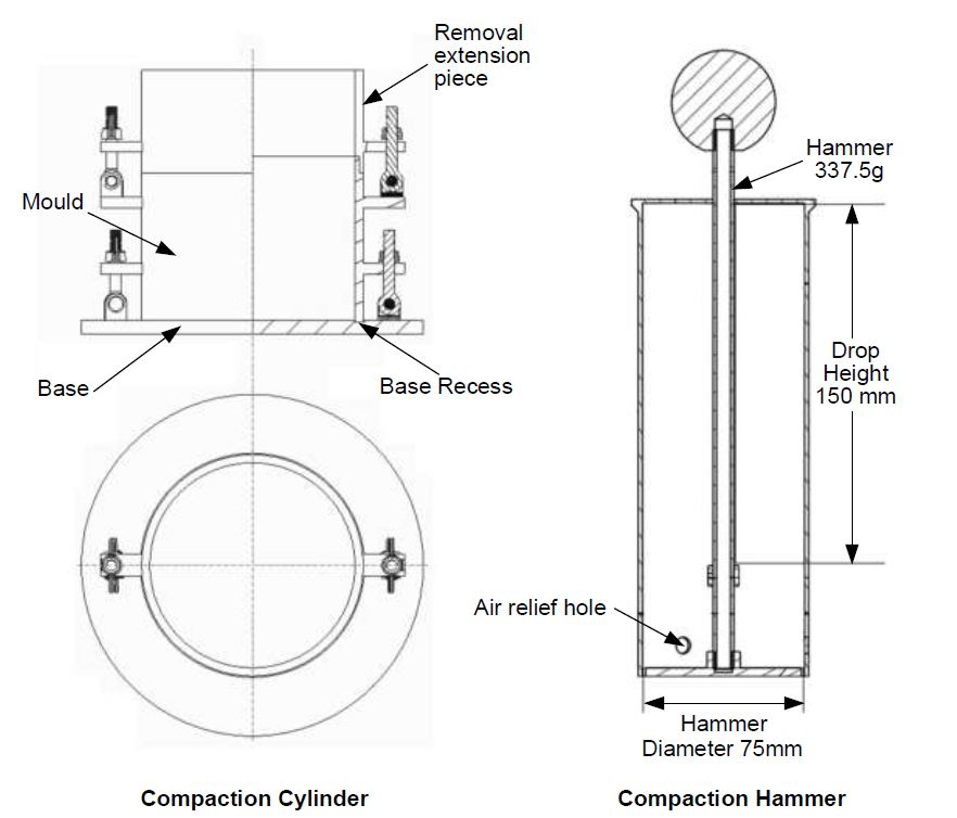
Figure 1.5.5.1.3.2 – Schematic of a Proctor/Fagerberg apparatus
1.5.5.1.4 Compaction hammer
A "D" energy equivalent compaction hammer is used for this test. Dimensions
are shown in figure 1.5.5.1.3.2 and table 1.5.6.2 (Note: the compaction hammer has been
modified to match the mould used.)
1.5.5.1.5 Drying oven
The drying oven should be ventilated, with forced circulation of air or
inert gas, typically with a stainless-steel interior and capable of maintaining a
temperature within the range of 105°C ± 5°C.
1.5.5.1.6 Weighing balance
The weighing balance should be capable of weighing the sample and the
container, as received, with an accuracy of better than ± 5 g.
1.5.5.1.7 Pycnometer
Water pycnometry equipment is used to determine the density of the
full-sized coal (non-crushed) in accordance with AS 1289.3.5.1:2006. Specific equipment
required is as follows:
-
– a conical flask or density bottle of 250 mL capacity;
-
– a vacuum desiccator or other vacuum equipment;
-
– a drying oven set to 105°C to 110°C;
-
– balances: one with ± 0.05 g accuracy and the second with ± 1 g accuracy;
-
– a 0°C to 100°C thermometer;
-
– a 2.36 mm sieve (as noted in 1.5.5.1.2)
-
– a vacuum source;
-
– a water bath set at 60°C;
-
– distilled, demineralized or deionized water;
-
– a wash bottle containing water;
-
– a wire basket to hold the + 2.36 mm sample;
-
– a container filled with water to hold the wire basket without interference;
and
-
– a scale to weigh the basket both suspended in water and drained.
1.5.5.1.8 Containers for hand mixing and sample preparation
Sufficient heavy-duty plastic buckets with lids of not less than 10 L
capacity are required for storage and handling. Heavy-duty plastic bags (200 micron
thick or greater) are required for storage and hand mixing of samples.
1.5.5.1.9 Flat scraping device
A thin steel scraper is required for separating the remnant sample formed
in the extension piece lying above the top level of the mould. For ease of use, the
scraper should have dimensions of 160 mm wide, 200 mm long and 3 mm to 5 mm thick, such
as that shown in figure 1.5.5.1.9.

Figure 1.5.5.1.9 – Typical scraping device
1.5.5.1.10 Drying trays
Drying trays or pans should have a smooth surface, be free from
contamination and heat resistant, for example stainless steel or enamel. Dimensions
should be suitable to fit in the drying oven and ensure that the total sample can be
contained at a loading of about 1 g/cm2 of surface area.
1.5.5.1.11 Spray bottle
A suitable plastic bottle is required to add a mist spray of water to the
sample.
1.5.5.1.12 Gloves
Heat resistant gloves are required for removal of hot trays and dishes.
1.5.5.1.13 Sample divider
A suitable sample divider as specified in ISO 13909-4:2001 is required for
sub-sampling the primary sample and blending the reconstituted sample for testing.
1.5.5.2 Sampling and sample preparation
1.5.5.2.1 General
This procedure commences with receipt of sample of not less than 170 kg,
sealed in a heavy duty (200 micron thick) plastic bag and contained in a suitable drum
(e.g. 220 L). This packaging ensures the sample does not dry prior to TML determination.
1.5.5.2.2 Sample preparation
Representative samples are required that have been obtained using ISO
13909-4:2001 and if required may be partially air dried or partially dried at a
temperature of 40°C or less to reduce the water content to a starting point suitable for
dry sieving the coal with minimal fines adhering to the oversize fraction. For this
purpose, samples should not be dried below 6% total moisture. The representative
subsamples for the test should not be fully dried, except in the case of gross water
content determination.
1.5.5.2.2.1 Sample homogenization and division
Take the as-received sample and divide into individual subsamples using a
sample dividing apparatus as specified in ISO 13909-4:2001. Place these subsamples into
heavy-duty plastic bags.
1.5.5.2.2.2 Reconstituted sample preparation procedure
When the sample contains particles above 25 mm, the reconstitution process
below should be applied.
In this process, particles above 25 mm are removed from the sample and
replaced by an equivalent mass of particles in the range 16 mm to 25 mm. Through this
process a final reconstituted sample of sufficient mass for TML testing is generated
which contains a maximum particle size of 25 mm.
One of two methods may be selected to generate the reconstituted sample:
-
.1 Split the entire as-received sample and then reconstitute; or
-
.2 Scalping off particles above 25 mm and substituting particles
between 16 mm and 25 mm from a separate subsample.
-
Method 1 Splitting the full as-received sample and
reconstitution
Step 1 Take the full as-received sample.
Step 2 Screen at 25 mm, 16 mm and 2.36 mm. If a 2.36 mm screen is
not available, a 2 mm screen may be used.
Step 3 Weigh each of the four size fractions and calculate the
percentage represented by each size fraction.
Step 4 Sub-divide from each size fraction below 25 mm the required
mass to create a 25 kg reconstituted sample using the sample size components
specified in table 1.5.5.2.2.2.1.
Table 1.5.5.2.2.2.1
Reconstitution size proportions (Method 1)
| Size fraction
|
Quantity
|
| -2.36 mm (or -2 mm)
|
percentage of this fraction in the original
sample
|
| 2.36 mm (or 2 mm) to 16 mm
|
percentage of this fraction
|
| 16 mm to 25 mm
|
percentage of this fraction plus the percentage of
+ 25 mm coal
|
Step 5 Combine each size fraction.
Step 6 Fully mix the reconstituted sample.
Step 7 Split the sample into approximately eight representative
subsamples and place each into a heavy duty plastic bag. These bags now contain
the sample for Proctor/Fagerberg testing.
Step 8 A sample of particles passing a 2.36 mm screen (or 2 mm if
2.36 mm is not available) is required for particle density pycnometry.
-
Method 2 Scalping particles above 25 mm and replacement with 16
mm to 25 mm particles
This method is described in figure 1.5.5.2.2.2 and table
1.5.5.2.2.2.2. The reconstitution process commences where the coal is initially
sieved into particle sizes larger than 25 mm and smaller than 25 mm. Coal
particles in the size range of 16 mm to 25 mm are extracted from separate
subsamples and reconstituted back into the original - 25 mm screened coal based
on a mass equivalent to the + 25 mm sized coal removed from the initial sample
to provide a final reconstituted sample of sufficient mass for TML testing.
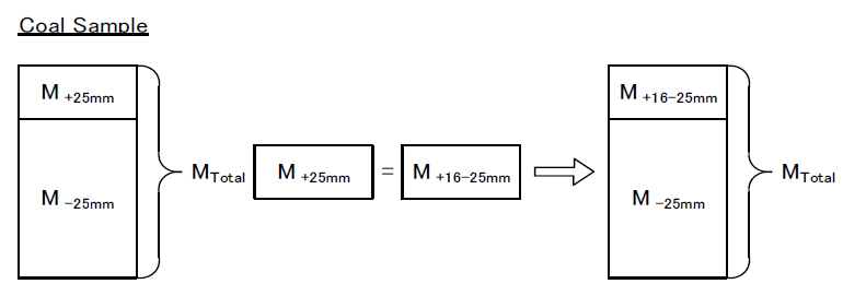
Figure 1.5.5.2.2.2 – Overview of sample reconstitution (Method 2)
Table 1.5.5.2.2.2.2
Sample reconstitution (Method 2)
| Step
|
Example
|
| 1
Generate a sample of approximately 25 kg which is sufficient to
complete approximately eight Proctor/Fagerberg tests.
|
Assumes each subsample bag contains 8 kg to 10 kg.
|
| 2
Screen this sample at 25 mm, ensuring minimal adhering fines on the
+ 25 mm fraction. Weigh the + 25 mm coal.
|
For a coal containing 20% + 25 mm material, approximately 5 kg of
initial sample is removed.
|
| 3
Create sufficient 16 mm to 25 mm coal by screening one or more
further subsample bags of coal at 16 mm and 25 mm.
|
In the above example, 5 kg of 16 mm to 25 mm coal is
required.
|
| 4
Extract an amount of 16 mm to 25 mm coal of mass equal to the mass
of + 25 mm removed in step b) within ± 0.05 kg using a rotary
sample divider or similar device, recombining sector trays as
required to obtain the required mass.
|
5 kg in the above case.
|
| 5
Add the mass of 16 mm to 25 mm coal from step d) to the -25 mm coal
from step 2. Blend and divide into approximately eight test
portions using a rotary sample divider or similar device.
|
|
6
Place each reconstituted test portion in heavy duty plastic bags,
label and seal.
These now become the test
portions used for Proctor/Fagerberg testing.
|
Each bag should contain approximately 2.5 kg to 3 kg of
reconstituted - 25 mm coal.
|
| 7
Discard the + 25 mm and - 16 mm coal.
|
|
1.5.5.2.3 Initial moisture
Initial moisture is to be determined on a test portion from table
1.5.5.2.2.2.2 step 5 using the method provided in ISO 589:2008. This moisture
value provides a guide to the moisture steps required to develop the
Proctor/Fagerberg compaction curve.
1.5.5.2.4 Particle density measurement
In accordance with water pycnometer standard AS 1289.3.5.1:2006,
measure the density of solids on the full size range (non-crushed) coal. The
density of solids is used for determining the void ratio for plotting
compaction curves. The recommended methodology is described below:
-
.1 Generate a full particle size sample of approximately
10 kg, weigh and then screen the entire contents at 2.36 mm. If a 2.36
mm screen is not available, a 2 mm screen may be substituted. Record
the following:
-
.1 the total mass of the material;
-
.2 the mass of + 2.36 mm material; and
-
.3 the mass of - 2.36 mm material.
-
.2 Calculate the percentage of - 2.36 mm coal in the
sample.
-
.3 Divide the + 2.36 mm coal into two test portions using
sample dividing apparatus as specified in ISO 13909-4:2001 such as a
rotary sample divider. Place each test portion in a heavy duty plastic
bag and label.
-
.4 Divide the - 2.36 mm coal into two test portions, place
each test portion in a heavy duty plastic bag and label.
-
.5 Determine the density of solids of the + 2.36 mm
fraction following the method described in Section 5.2 of AS
1289.3.5.1:2006. As noted in the standard, duplicate determinations
are required.
-
.6 Determine the density of solids of the - 2.36 mm
fraction using the method described in Section 5.1 of the above
standard with the following clarifications:
-
.1 Use of 250 mm conical or pycnometry flasks
is recommended.
-
.2 From the sample bag pour 1 L of coal into a
beaker of known tare weight.
-
.3 Weigh the 1 L sample and calculate the
approximate bulk density of the material.
-
.4 Remove a portion of the sample (nominally a
mass in kilograms of 0.18 x bulk density) and place into the
flask, and complete the pycnometry analysis.
-
.5 A water bath temperature of 60°C is
recommended.
-
.7 Calculate the density of solids using the method in
Section 6 of AS 1289.3.5.1:2006.
1.5.5.3 Test procedure
1.5.5.3.1 Variables and definitions
The variables and definitions used in the determination of TML are
summarized in table 1.5.5.3.1 with some key variables as illustrated in figure
1.5.5.3.1.
Table 1.5.5.3.1 – Summary
of variables and definitions
| Variable
|
Unit
|
Symbol/value used in calculations
|
| Mass of empty cylinder and base
|
g
|
A
|
| Mass of cylinder, base and tamped test portion
|
g
|
B
|
| Wet mass of test portion in the mould
|
g
|
C = B − A
|
| Wet mass of test portion removed from the mould
|
g
|
C1
|
| Dry mass of test portion removed from the mould
|
g
|
D1
|
| Gross water content
|
%
|
W1
|
| Dry mass of test portion in the mould
|
g
|
D
|
| Mass of water in the mould
|
g
|
E
|
| Volume of cylinder
|
cm3
|
V
|
| Density of solids
|
g/cm3
|
d
|
| Density of water
|
g/cm3
|
ρw
|
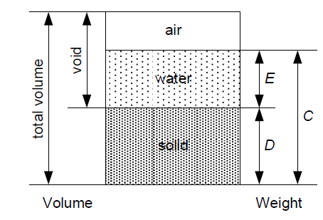
Figure 1.5.5.3.1 – Illustration of key variables
1.5.5.3.2 Establishment of the initial compaction point
The initial compaction point is obtained using the first test
portion of the reconstituted material at the initial moisture content. For each
compaction point determination, all steps in the procedure from packing the
mould to weighing the mould and sample are to be completed at the same time
without breaks. In any case, coal should not be left in the mould for longer
than 30 min prior to weighing.
The test procedure is as follows:
-
| Step 1
|
Clean the mould, collar and base plate.
Inspect and clean the hammer and ensure that it moves
freely in the guide tube.
|
| Step 2
|
Determine the mass, A, of the empty
cylinder, comprising the mould plus base plate.
|
| Step 3
|
Assemble the mould, collar and base plate and
place the assembly on a stable bench.
|
| Step 4
|
Place approximately 0.5 L (one fifth of the
full 2.5 L) of the test portion into the mould, level, and
then tamp uniformly over the surface by dropping the
hammer 25 times vertically through the full height of the
guide pipe, moving the guide pipe to a new position after
each drop. The required pattern for even compaction of
each layer in the mould is shown in figure
1.5.5.3.2.
|
| Step 5
|
Repeat step 4 four more times so that there
are 5 layers of material in the mould. Ensure that the
compacted test portion with the final layer is above the
top of the compaction mould whilst the extension piece is
still attached.
|
| Step 6
|
When the last layer has been tamped, remove
the extension piece taking care not to disturb the
compacted test portion inside. Level the compacted test
portion to the top of the mould using the flat scraping
device, ensuring that any large particles that may hinder
levelling of the test portion are removed and replaced
with material contained in the extension piece and
re-level. If any holes in the surface are still observed
after levelling, they should be manually filled with finer
material contained in the extension piece. Care should be
taken to avoid any further compaction of the test
portion.
|
| Step 7
|
Determine the mass, B, of the mould
and compacted coal and then calculate the mass, C,
of the wet test portion using the equation:
|
|
|

|
(1)
|
| Step 8
|
When the weight of the cylinder with the
tamped test portion has been determined, remove the test
portion from the mould, determine the mass of the wet test
portion, C1, and dry the entire test portion in
an oven at 105°C until constant mass is achieved. After
drying, determine the weight, D1, of the dried
test portion and then calculate the percentage gross water
content, W1, as follows:
|
|
|

|
(2)
|
| Step 9
|
Using the calculated gross water content,
calculate the mass of the dry test portion in the mould,
D, using the equation:
|
|
|

|
(3)
|
| Step 10
|
Calculate the mass, E, of water in the mould
using the equation:
|
|
|

|
(4)
|
| Step 11
|
Discard the used coal sample. Coal from a
previously compacted test portion should not be
reused.
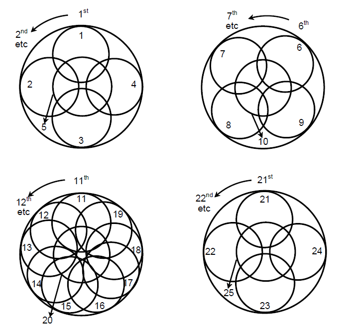
Figure 1.5.5.3.2 – Recommended compaction
patterns
|
1.5.5.3.3 Establishment of complete compaction curve
The range of water contents should be adjusted so that partially
dry to almost saturated test portions are obtained. Care should be taken to
follow the precaution in 1.5.5.3.2 above regarding prompt completion of each
point in the compaction curve.
The test procedure is as follows:
-
Step 1 For each compaction test, a predetermined amount of
water is added to the test portion (approximately 2.5 kg) in a heavy
duty plastic bag. The water quantity added is that required to
increase the moisture content to the target value for the next test.
The water should be added as a mist spray to the surface of the
individual test portions. The water at this point should be added
slowly and in small quantities, as the introduction of large amounts
of water may induce localized compaction behaviour.
-
Step 2 After the calculated water addition, the test
portion should then be mixed thoroughly in the plastic bag by sealing
the bag and turning it over repeatedly for 5 MIN.
-
Step 3 The test portion should then be allowed to
equilibrate for a minimum of 12 hours prior to compaction testing.
-
Step 4 Repeat steps 1 to 11 from 1.5.5.3.2.
-
Step 5 Repeat the test between four and seven times using
the other prepared test portions with different water contents to
obtain at least five points on the compaction curve. The water
contents should be chosen so that:
-
.1 at least one point corresponds to moisture
content higher than the optimum moisture content (OMC) or
than the value corresponding to 70% of degree of saturation
(S), in order to satisfactorily define the
compaction curve; and
-
.2 at least one point corresponds to the degree
of saturation (S) between 70% and 80%, in order to
effectively assess the PFD70 value.
A point close to a degree of saturation (S) of 80%
will also assist accurate assessment if the OMC is greater than 70%.
1.5.5.3.4 Visual appearance of coal in the cylindrical mould
In order for the test to obtain a PFD70 value, all tests conducted
at or below the PFD70 moisture value should have an even moisture distribution
throughout the cylindrical mould.
Two examples of tests using samples of the same coal at different
moisture contents are shown in figure 1.5.5.3.4.1. The left-hand photograph
shows a coal specimen at a relatively low degree of saturation. Note that the
coal remains in place following removal of the collar. The right-hand
photograph shows a specimen near or possibly above 70% degree of saturation.
Once again the coal remains in place following removal of the collar. Both
tests provided valid points on the compaction curve.

Figure 1.5.5.3.4.1 – Photographs showing valid tests for a partially
saturated test portion (left) and a near fully saturated test portion
(right)
Coals where water passes through the spaces between particles
exhibit moisture migration within the Proctor/Fagerberg cylindrical mould.
Moisture migration may take place when the degree of saturation of the specimen
is less than 70%.
Evidence of moisture migration is from visual observation at the
completion of each test as follows:
-
.1 moisture leakage from the base of the mould is evident
as shown in figure 1.5.5.3.4.2; and
-
.2 The portion above the top of the cylindrical mould
appears unsaturated and the test portion maintains its structure
without deformation or movement.
In this case, moisture migration has occurred and hence for this
coal water passes through the spaces between particles.
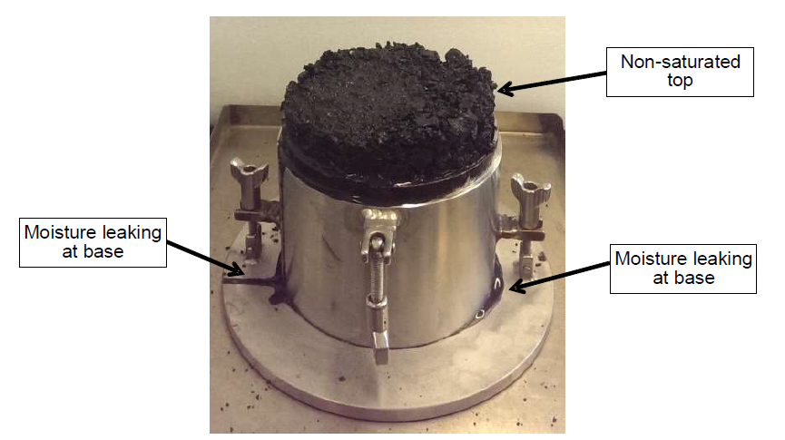
Figure 1.5.5.3.4.2 – Test showing water leakage from the base of the
cylindrical mould indicating moisture migration
1.5.5.3.5 Calculation of key parameters for determination of
compaction curve
Carry out the following calculations for each compaction test:
|
d |
= |
density of solids, g/cm3 (t/m3) by
pycnometry (see 1.5.5.2.4) |
|
γ |
= |
dry bulk density, g/cm3
(t/m3) |
| = |
D/V |
|
ev |
= |
net water content (percentage by volume) |
| = |
(E/D) × 100 × d/ρw
where ρw= density of water,
g/cm3 (t/m3)
|
|
e |
= |
void ratio (volume of voids divided by volume of
solids) |
| = |
(d/γ) -1 |
|
S |
= |
degree of saturation (percentage by volume) |
| = |
ev /e |
|
W1 |
= |
gross (total) water content (percentage by mass) (see
1.5.5.3.2, Step 8). |
1.5.5.3.6 Presentation of compaction results
Record all the compaction test results in a suitable spreadsheet
(such as that shown in table 1.5.6.1) and from this spreadsheet create a
compaction curve as shown in figure 1.5.5.3.6 by plotting the calculated void
ratio (e) for each compaction test on the ordinate against either the
net or gross water content plotted on the abscissa.
The lines in figure 1.5.5.3.6 correspond to plots of void ratio
(e) versus net water content (ev) at 20%,
40%, 60%, 70%, 80% and 100% degree of saturation (S). These lines are
calculated at five values of void ratio using the formulae in 1.5.5.3.7. (Note:
These lines corresponding to degree of saturation will be curved in the case of
plotting gross water content on the abscissa.)
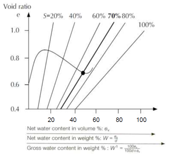
Figure 1.5.5.3.6 – Typical compaction curve
1.5.5.3.7 Sample compaction curve
An example of the results obtained when applying the Modified
Proctor/Fagerberg test to a coal sample is provided in table 1.5.6.1, with the
corresponding compaction curve and the 70% degree of saturation line plotted as
described below.
The preferred approach to presenting the results is to plot the
void ratio (
e) against the gross water content (
W1)
allowing moisture for any saturation level to be read directly from the plot as
gross water content. This approach is shown in figure 1.5.5.3.7. The saturation
lines are plotted according to the equation:
The intercept of the compaction curve with the 70% degree of
saturation line in figure 1.5.5.3.7 occurs at a gross water content of 15.4%,
which is the transportable moisture limit (TML). For this example, the optimum
moisture content (OMC) occurs at a degree of saturation of about 85%.
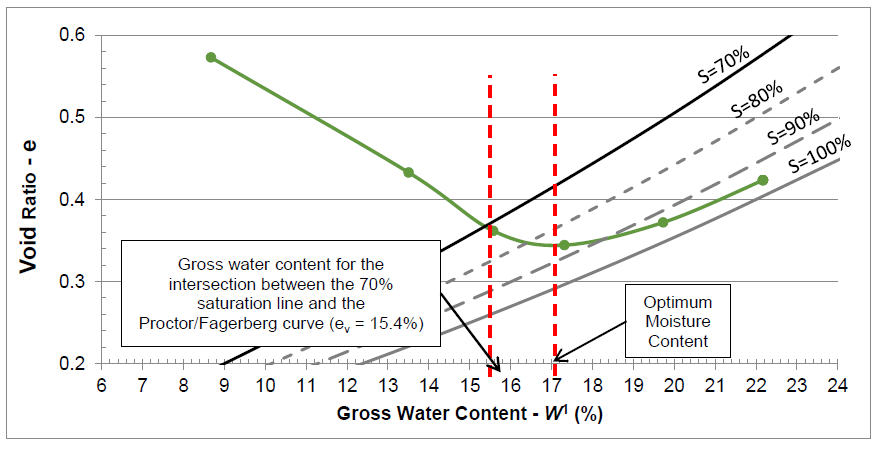
Figure 1.5.5.3.7 – Example of a measured compaction curve for void ratio
versus gross water content with the 70%, 80%, 90% and 100% degree of
saturation lines plotted
1.5.5.3.8 Determination of transportable moisture limit
1.5.5.3.8.1 Determination of PFD70 moisture content
The PFD70 value is determined as the gross (total) water content
corresponding to the intersection of the compaction curve and the line S
= 70% saturation. The optimum moisture content (OMC) is the gross (total)
moisture content corresponding to the maximum compaction (maximum dry density
and minimum void ratio) under the specified compaction condition.
The test procedure is applicable for determination of coal TML
where the degree of saturation corresponding to the OMC of the coal is at or
greater than 70%. Where the OMC lies below 70% degree of saturation, this test
is not applicable for the specific coal and the PFD70 may overstate the TML. In
such cases, the certificate of analysis should state that the OMC is below 70%
saturation and the shipper should consult with an appropriate authority.
1.5.5.3.8.2 Cases where the highest determinable point on the
compaction curve lies below 70% saturation
In coals where there is visual evidence that water passes through
the spaces between particles and the compaction curve does not extend to or
beyond the 70% degree of saturation line, the coal is deemed to be
free-draining and a TML value is not applicable. By reference to 7.2.2 of this
Code, such coals are cargoes which are not liable to liquefy, and hence are
classified as group B only.
1.5.6 Test report
The test report from application of the modified Proctor/Fagerberg
test procedure should include the following information:
-
.1 identification of the sample;
-
.2 a unique reference to this test procedure;
-
.3 reference to the appropriate standard adopted for
determining the density of the solids:
either:
-
.1 the transportable moisture limit (TML) of the
sample, expressed as the gross water content as a percentage of the
sample by mass;
-
.2 the OMC lies below 70% degree of saturation and this
test procedure is not applicable; or
-
.3 a statement that the test indicated that water
passes through the spaces between particles at moisture content
below the value corresponding to 70% degree of saturation, and the
coal is therefore group B only.
-
.4 The solids density d in g/cm3.