6.2.1 On typical bulk carriers, the topside and
bilge hopper tanks compose a double hull surrounding the cargo space,
which together with the double bottom provide hull strength and rigidity.
Single hulled side shells provided with individual transverse frames
are located between the topside and bilge hopper tanks. In recent
designs, these hold frames and end brackets are thinner than the side
shell and are not constructed with web frames and side stringers as
is the case with general cargo carriers.
Below is a comparison of thickness of hull skin plates and hold
frames in cargo hold.
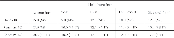
Figure 11 Comparison of thickness of hull skin and hold frames
6.2.2 Corrosion generally attacks thinner steel
structures and is accelerated in thinner plates. During the time a
thicker steel plate loses half of its original thickness, a thinner
plate might corrode completely.
6.2.3 Among the various members composing cargo
hold structures, the hold frames are usually the thinnest structures
especially at the web plates In addition, the hold frames also have
more surface area exposed, in that both surfaces of the plate are
susceptible.
6.2.4 This may mean accelerated corrosion in the
hold frames, the thinnest among all the members in cargo holds. If
corrosion and waste become excessive, failure of hold frames invites
additional loads to the adjacent ones, which may lead to failure throughout
the side shell structure.
6.2.5 Transverse bulkheads may also be susceptible
to accelerated corrosion, particularly at the midheight and at the
bottom. Particular care should be exercised when inspecting hold frames
and transverse bulkheads, in that these members may appear in deceptively
good condition. Tanktop and side shell plating generally corrode from
the steel surface facing the cargo hold and corrosion from inside
the double bottom is usually less than that from cargo hold side.
6.2.6 Regarding the corrosiveness of cargoes,
coal is among the most corrosive cargoes carried on board the bulk
carriers. Thickness measurement surveys revealed that bulk carriers
which have been employed in carriage of coal suffer more serious corrosion
to their cargo holds than those engaged in the carriage of any other
cargoes.
6.2.7 Cargo hold frames should also be carefully
inspected for mechanical damage, corrosion and waste because many
cargoes will damage hold frames through direct contact. This damage
will invite corrosion from seawater brought on board in loading operations.
6.2.8 The most important aspects of cargo hold
inspections are the condition of side shell structures and their reinforcements.
Special attention should be paid to the condition of hold frames and
their connection to the shell plating.
Transbulkheads and associated structures
6.2.9 Bulk carrier watertight transverse bulkheads
at the ends of dry cargo holds are constructed in various ways which
in general can be categorized as either vertically corrugated with
or without upper or lower stools, double plated with or without upper
or lower stools, or plane bulkheads vertically stiffened.
6.2.10 It may be necessary that certain holds
bounded by the foregoing categories of bulkheads are partially filled
with water ballast in order to achieve a satisfactory air draught
at the loading/discharge berths. The filling is restricted to correspond
to the dry cargo hold scantlings. However, for deep tank corrugated
bulkheads at the ends of cargo holds which are designed to be fully
filled with water ballast the scantlings are increased substantially
from that for ordinary watertight transverse bulkheads.
6.2.11 The opportunity is taken to emphasize that
for ordinary transverse watertight bulkheads, in addition to withstanding
water pressure in an emergency situation, i.e., flooding, the bulkhead
structures constitute main structural strength elements in the structural
design of the intact vessel. Ensuring that acceptable strength is
maintained for these structures is therefore of major importance.
6.2.12 The structure may sometimes appear to be
in good condition when it is in fact excessively corroded. In view
of this, appropriate access arrangements should be provided to enable
a proper close-up inspection and thickness assessment.footnote
6.2.13 It is imperative to realize that in the
event of one hold flooding, the transverse watertight bulkheads prevent
progressive flooding and therefore also prevent the ship from sinking.
6.2.14 The following are examples for the more
common damage/defects that may occur:
-
.1
Fractures
at
the boundaries of corrugations and bulkhead stools particularly in
way of shelf plates, shedder plates, deck, inner bottom, etc.
-
.2
Buckling of the plating/corrugations
leading to the failure and collapse of the bulkhead under water pressure
in an emergency situation.
-
.3
Excessive wastage/corrosion, in
particular at the midheight and at the bottom of bulkheads which may
look in deceptively good condition. This is created by the corrosive
effect of cargo and environment, in particular, when the structure
is not coated. In this respect special attention should be given to
the following areas:
-
.1 bulkhead plating adjacent to the shell plating;
-
.2 bulkhead trunks which form part of the venting,
filling and discharging arrangements between the topside tanks and
the hopper tanks;
-
.3 bulkhead plating and weld connections to the
lower/upper stool shelf plates;
-
.4 weld connections of stool plating to the lower/upper
stool shelf plates and inner bottom;
-
.5 in way of weld connections to topside tanks
and hopper tanks;
-
.6 any areas where coatings have broken down and
there is evidence of corrosion or wastage. It is recommended that
random thickness determination be taken to establish the level of
diminution; and
-
.7 other structures, e.g., diaphragms inside the
stools, particularly at their upper and lower weld connections.
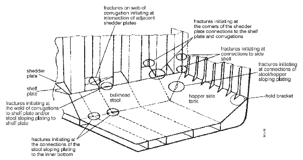
Figure 13 Typical fracturing at the connection of transverse bulkhead
structure
Damages caused by cargoes
6.2.15 In cargo holds, tanktop plating and side
shell structures are apt to be damaged by cargo handling operations.
6.2.16 At loading and unloading ports for coal
or iron ore, large grab buckets, high capacity cargo loaders, bulldozers
and pneumatic hammers may be employed for cargo handling operations.
6.2.17 Large grab buckets may cause considerable
damage to tanktop plating when being dropped to grab cargo. Use of
bulldozers and pneumatic hammers may also be harmful to cargo hold
structures and may result in damage to tanktops, bilge hoppers, hold
frames and end brackets.
6.2.18 Lumber cargoes may also cause damage to
the cargo hold structures of smaller bulkers that are employed in
the carriage of light bulk cargoes and lumbers.
Cracking
-
6.12.19.1
Combination cargo/ballast hold
In bulk carriers having combination cargo/ballast holds, cracks
may often be found at or near the connection of the stool of the transverse bulkhead
and the tank top.
All the capesize and panamax bulk carriers and some of handy
bulkers have combination cargo/ballast hold(s) to keep the necessary
draught. The bulkhead boundaries of the spaces are designed to comply
with the requirements for deep tank bulkheads. In these holds cracks
may often be found at the connection between the transverse bulkhead
and the tanktop. These cracks can be detected by visual inspection
or by noting leakage from the double bottom tanks.
-
6.12.19.2
Others
Side stringers and/or side shells in way of No. 1 cargo hold
along the collision bulkhead are
often found cracked. This kind of damage is considered to be caused
by insufficient continuity between fore peak construction and cargo
hold structure.
On large bulk carriers such as capesize and panamax bulkers,
bilge hopper plating around the knuckle line may be cracked along
the bilge hopper transverse
webs. This is considered to be caused by insufficient local reinforcement.
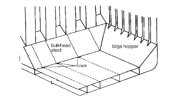
Figure 14 Cracking at the connection of bulkhead stool and tanktop
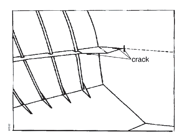
Figure 15 Cracking around the collision bulkhead
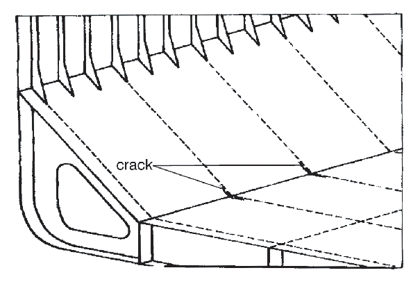
Figure 16 Cracking in bilge hopper