
Section 1 Calculation procedure
1.3 Hence, maximum
bending moment, M
S' is given by:
Assumed shell laminate:
5 x 800/300 combination
mats
|
G
c
|
= |
0,5 (WR in combination mat) |
|
G
c
|
= |
0,33 (CSM in combination mat) |
1 x 450 CSM adjacent to gel coat
Total thickness, t
p = 9,132
mm
The effective width of attached plating 2b
1 from Pt 8, Ch 3,1.7.1 of the Rules for Special Service Craft
for single skin construction is:
|
b
1
|
= |
0 . 5b
w + 10t
ap
|
| = |
0,5 x 120 + 10 x 9,132 |
| = |
151 mm |
Hence, apply 302 mm attached plating.
Consider
typical layup over ‘top hat’ stiffener:
| 450 g/m2 CSM
|
@
|
G
c = 0,33 – first ply over former
|
| 800 g/m2 WR
|
@
|
G
c = 0,5
|
| 800 g/m2 WR
|
@
|
G
c = 0,5
|
| 600 g/m2 UDT
|
@
|
G
c = 0,54
|
| 600 g/m2 UDT
|
@
|
G
c = 0,54
|
| 800 g/m2 WR
|
@
|
G
c = 0,5
|
| 800 g/m2 WR
|
@
|
G
c = 0,5 – top ply
|
1.5 The stiffener
bonding is to be in accordance with Pt 8, Ch 3, 1 General of the Rules for Special Service Craft and a typical
arrangement is shown in Figure 5.1.3 Typical stiffener bonding arrange.
To simplify the calculation of the stiffness of the overall section
the tapered bonding is assumed to be an effective constant thickness.
1.6 The effective thickness of the bonding is calculated
as:
The boundary bonding may be approximated to a thickness
of 3,15 mm over an (85 x 2) mm width to account for both flanges.
The majority of the flange comprises of woven rovings and it may be
assumed that the tensile modulus is 145000 N/mm2. The discrepancy
is negligible since the element is very close to the neutral axis.
1.7 The effective depth and width of the
web used in the idealised section are:
|
d
web
|
= |
70 – effective thickness on bonding |
|
t
web
|
= |
2 x (0,937 + 4 x 0,979) |
1.8 Now the web consists of two types of reinforcements,
namely one ply of CSM and four plies of woven rovings. The majority
of the web will be in compression and the overall modulus of elasticity
may be calculated in accordance with Pt 8, Ch 3, 1 General of the Rules for Special Service Craft.
The web may now be treated as a single laminate item
having an overall compressive modulus, given above.
1.9 The laminate
section modulus calculation is shown in Table 5.1.1 Initial tabulation of 'top-hat'
stiffener calculations. The tabulation consists of each element having the compressive
moduli in the section above the neutral axis and tensile moduli below.
The actual breadth of each element must be entered to calculate the
overall section properties. The tabulation corresponds to the idealised
section in Figure 5.1.2 Idealised section.
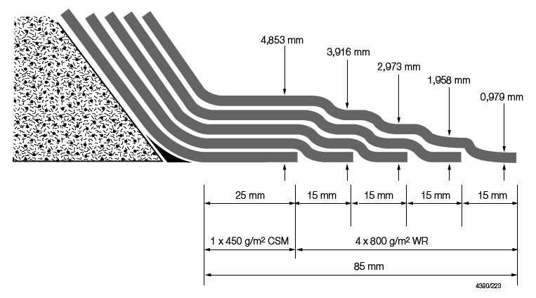
Figure 5.1.3 Typical stiffener bonding arrange
1.10 The tabulation
considers the entire section and calculates all moments about the
base, which is taken to be the outer (wet) surface. The stiffness, EI, of the entire section, about the neutral axis, is determined
using the parallel axis theorem:
In general,
|
EI
sect
|
= |
ΣEI
base – (Σ Etb)
x y
2
|
where
|
y
|
= |
distance
of neutral axis above the base (mm) |
1.11 From the tabulation:
|
EI
sect
|
= |
70480944121 – 53219882 x (22,44)2
|
|
EI
sect
|
= |
4,368 x 106 Ncm4/mm2
|
1.12 From Pt 8, Ch 3, 1 General of the Rules for Special Service Craft the individual
layer stresses are determined from:
The calculation of the stresses in individual layers
becomes:
where
|
E
i
|
= |
modulus of elasticity of layer (N/mm2)
|
|
y
i
|
= |
distance of layer from the neutral axis (mm) |
Table 5.1.1 Initial tabulation of 'top-hat'
stiffener calculations
|
|
Ply No.
|
Description
|
G
c
|
Weight
|
t
|
Breadth,
|
Lever @
|
E
|
t.b
|
E.t.b
|
E.t.b.x
|
I @
|
EI @
|
|
|
(g/m2)
|
(mm)
|
b (mm)
|
base, x (mm)
|
(N/mm2)
|
|
|
|
base
|
base
|
Dry
see Note
|
1
|
WR
|
0,5
|
800
|
0,979
|
80
|
84,816
|
14000
|
78,32
|
1096480
|
92998499
|
563414,4
|
7887801805
|
|
|
2
|
WR
|
0,5
|
800
|
0,979
|
80
|
83,837
|
14000
|
78,32
|
1096480
|
91925046
|
550483,0
|
7706761655
|
|
|
3
|
UDT
|
0,54
|
600
|
0,660
|
80
|
83,017
|
20748
|
52,80
|
1095494
|
90944659
|
363890,1
|
7549992490
|
|
|
4
|
UDT
|
0,54
|
600
|
0,660
|
80
|
82,357
|
20748
|
52,80
|
1095494
|
90221632
|
358127,2
|
7430422738
|
|
|
5
|
WR
|
0,5
|
800
|
0,979
|
80
|
81,538
|
14000
|
78,32
|
1096480
|
89404238
|
520706,1
|
7289885632
|
|
|
6
|
WR
|
0,5
|
800
|
0,979
|
80
|
80,559
|
14000
|
78,32
|
1096480
|
88330784
|
508277,4
|
7115883045
|
|
|
7
|
CSM
|
0,33
|
450
|
0,937
|
80
|
79,601
|
7200
|
74,96
|
539712
|
42961345
|
474970,0
|
3419784035
|
|
|
8
|
Web
|
0,5
|
–
|
66,85
|
9,706
|
45,707
|
12687
|
648,85
|
8231910
|
376255932
|
1597160,7
|
20263177372
|
|
|
9
|
bonding
|
0,5
|
–
|
3,15
|
170
|
10,707
|
14500
|
535,50
|
7764750
|
83137178
|
61832,4
|
896570245
|
|
|
10
|
WR
|
0,5
|
800
|
0,979
|
302
|
8,643
|
14500
|
295,66
|
4287041
|
37050752
|
22107,1
|
320553529
|
|
|
11
|
CSM
|
0,33
|
300
|
0,625
|
302
|
7,840
|
6950
|
188,75
|
1311813
|
10285266
|
11609,3
|
80684330
|
|
|
12
|
WR
|
0,5
|
800
|
0,979
|
302
|
7,039
|
14500
|
295,66
|
4287041
|
30174338
|
14670,7
|
212724485
|
|
|
13
|
CSM
|
0,33
|
300
|
0,625
|
302
|
6,236
|
6950
|
188,75
|
1311813
|
8181119
|
7347,4
|
51064249
|
|
|
14
|
WR
|
0,5
|
800
|
0,979
|
302
|
5,435
|
14500
|
295,66
|
4287041
|
23297924
|
8755,5
|
126954976
|
|
|
15
|
CSM
|
0,33
|
300
|
0,625
|
302
|
4,632
|
6950
|
188,75
|
1311813
|
6076971
|
4056,7
|
28194272
|
|
|
16
|
WR
|
0,5
|
800
|
0,979
|
302
|
3,831
|
14500
|
295,66
|
4287041
|
16421511
|
4361,7
|
63245002
|
|
|
17
|
CSM
|
0,33
|
300
|
0,625
|
302
|
3,028
|
6950
|
188,75
|
1311813
|
3972824
|
1737,3
|
12074400
|
|
|
18
|
WR
|
0,5
|
800
|
0,979
|
302
|
2,227
|
14500
|
295,66
|
4287041
|
9545097
|
1489,3
|
21594564
|
|
|
19
|
CSM
|
0,33
|
300
|
0,625
|
302
|
1,424
|
6950
|
188,75
|
1311813
|
1868677
|
389,2
|
2704632
|
Wet
see Note
|
20
|
CSM
|
0,286
|
450
|
1,112
|
302
|
0,556
|
6290
|
335,82
|
2112333
|
1174457
|
138,4
|
870664
|
| TOTALS
|
|
|
|
|
85,305
|
|
|
|
4436,05
|
53219882
|
1194228249
|
|
70480944121
|
Note Position of neutral axis above base  22,44 mm above base Tensile modulus of elasticity
of section 22,44 mm above base Tensile modulus of elasticity
of section  11997 N/mm2 11997 N/mm2
Note Stiffness EI of section about NA = 4368304 N
cm4/mm2
|
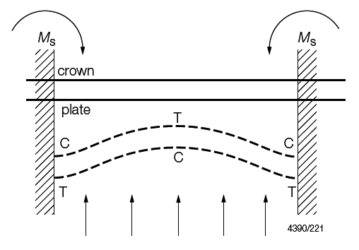
Figure 5.1.4 Regions of tension (T) and compression (C) in example model
|