A suitable test rig is illustrated in Figures 1 and 2. It shall consist of two rectangular
frames hinged together and capable of being locked at right angles
to each other.
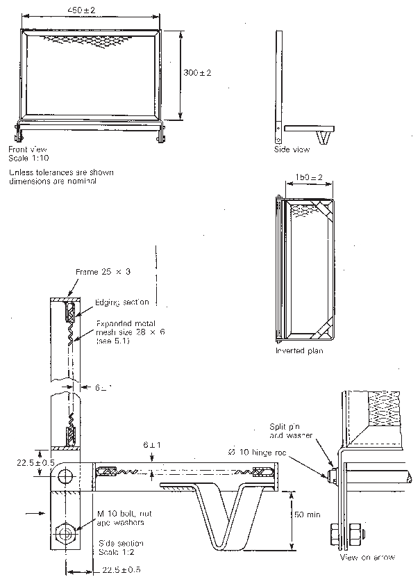
Figure 1 Test rig
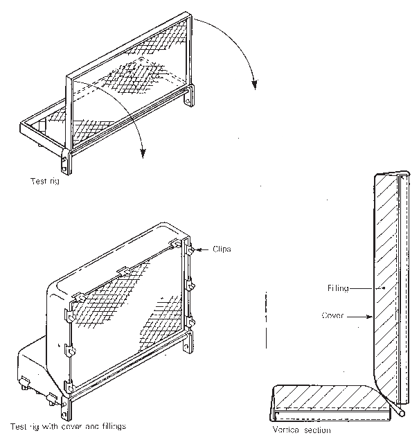
Figure 2 Test rig assembly
The frames shall be made from nominal 25 mm x 3 mm steel
flat bar and shall securely hold expanded steel platforms set 6 ±
1 mm below the top edge of the frames.
Note:
The size of the mesh of the
expanded steel is not critical, but a mesh size across the diagonals
of approximately 28 mm x 6 mm has been found to be suitable.
The internal width and height of the back frame shall be
450 ± 2 mm x 300 ± 2 mm and the width and depth of the
base frame 450 ± 2 mm x 150 ± 2 mm. A standard edging
section may be used around the expanded steel to give protection and
greater rigidity.
The sides of the frame shall extend beyond the back of each
frame to provide for the hinge holes and to form the back legs. The
hinge rod shall be of nominal l00 mm diameter steel, continuous across
the back of the rig, and its axis 22.5 ± 0.5 mm beyond the
back member of each frame.
The frames shall be lockable at right angles by a bolt or
pin through each of the pairs of members forming the back legs. The
front legs may be welded across the front corners of the base frame.
The height of the legs shall be such as to leave a gap not less than
50 mm high between the base frame and the supporting surface.
For the tests, the rig shall be sited within the enclosure
(see 4.2) and the testing shall
be performed in a substantially draught-free environment permitting
an adequate supply of air.