16.1 General


                        16.1.1 The manufacture, testing, inspection and documentation shall be
                           in accordance with recognized standards and the regulations given in this Code. 


                         16.1.2 Where post-weld heat treatment is specified or required, the properties of the
                           base material shall be determined in the heat treated condition, in accordance with
                           the applicable tables of chapter 7, and the weld properties shall be determined in
                           the heat treated condition in accordance with 16.3. In cases where a post-weld heat
                           treatment is applied, the test regulations may be modified at the discretion of the
                           Administration.


                        16.2 General test regulations and
                           specifications


                        16.2.1 Tensile test 


                        16.2.1.1 Tensile testing shall be carried out in accordance with
                           recognized standards. 


                        16.2.1.2 Tensile strength, yield stress and elongation shall be to the
                           satisfaction of the Administration. For carbon-manganese steel and other materials
                           with definitive yield points, consideration shall be given to the limitation of the
                           yield to tensile ratio. 


                         16.2.2 Toughness test 


                        16.2.2.1 Acceptance tests for metallic materials shall include Charpy V-notch
                           toughness tests unless otherwise specified by the Administration. The specified
                           Charpy V-notch regulations are minimum average energy values for three full size (10
                           mm × 10 mm) specimens and minimum single energy values for individual specimens.
                           Dimensions and tolerances of Charpy V-notch specimens shall be in accordance with
                           recognized standards. The testing and regulations for specimens smaller than 5.0 mm
                           in size shall be in accordance with recognized standards. Minimum average values for
                           sub-sized specimens shall be:


                                    | Charpy V-notch specimen size (mm) | Minimum average energy of three
                                       specimens | 
                                 
                                    | 10 x 10 | KV | 
                                 
                                    | 10 x 7.5 | 5/6 KV | 
                                 
                                    | 10 x 5.0 | 2/3 KV | 


                           - where:
- KV = the energy values (J) specified in tables 7.1 to 7.4.
Only one individual value may be below the specified average value, provided it is
                           not less than 70% of that value.


                        16.2.2.2 For base metal, the largest size Charpy V-notch specimens possible for the
                           material thickness shall be machined with the specimens located as near as
                           practicable to a point midway between the surface and the centre of the thickness
                           and the length of the notch perpendicular to the surface as shown in figure
                           16.1.


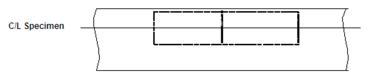
                           Figure 16.1 – Orientation of base metal test specimen


                        16.2.2.3 For a weld test specimen, the largest size Charpy V-notch specimens possible
                           for the material thickness shall be machined, with the specimens located as near as
                           practicable to a point midway between the surface and the centre of the thickness.
                           In all cases the distance from the surface of the material to the edge of the
                           specimen shall be approximately 1 mm or greater. In addition, for double-V butt
                           welds, specimens shall be machined closer to the surface of the second welded
                           section. The specimens shall be taken generally at each of the following locations,
                           as shown in figure 16.2, on the centreline of the welds, the fusion line and 1 mm, 3
                           mm and 5 mm from the fusion line.


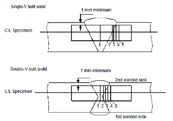
                           Figure 16.2 – Orientation of weld test specimen


                        Notch locations in figure 16.2: 


                           - .1 centreline of the weld; 
- .2 on fusion line; 
- .3 in heat-affected zone (HAZ), 1 mm from fusion line; 
- .4 in HAZ, 3 mm from fusion line; and 
- .5 in HAZ, 5 mm from fusion line.
16.2.2.4 If the average value of the three initial Charpy V-notch specimens fails to
                           meet the stated regulations, or the value for more than one specimen is below the
                           required average value, or when the value for one specimen is below the minimum
                           value permitted for a single specimen, three additional specimens from the same
                           material may be tested and the results combined with those previously obtained to
                           form a new average. If this new average complies with the regulations and if no more
                           than two individual results are lower, than the required average and no more than
                           one result is lower than the required value for a single specimen, the piece or
                           batch may be accepted. 


                         16.2.3 Bend test 


                        16.2.3.1 The bend test may be omitted as a material acceptance test, but
                           is required for weld tests. Where a bend test is performed, this shall be done in
                           accordance with recognized standards. 


                         16.2.3.2 The bend tests shall be transverse bend tests, which may be
                           face, root or side bends at the discretion of the Administration. However,
                           longitudinal bend tests may be required in lieu of transverse bend tests in cases
                           where the base material and weld metal have different strength levels. 


                        16.2.4 Section observation and other testing 


                        Macrosection, microsection observations and hardness tests may also be
                           required by the Administration, and they shall be carried out in accordance with
                           recognized standards, where required.


16.3 Welding of metallic materials
                           and non-destructive testing for the fuel containment system


                         16.3.1 General 


                        This section shall apply to primary and secondary barriers only,
                           including the inner hull where this forms the secondary barrier. Acceptance testing
                           is specified for carbon, carbon-manganese, nickel alloy and stainless steels, but
                           these tests may be adapted for other materials. At the discretion of the
                           Administration, impact testing of stainless steel and aluminium alloy weldments may
                           be omitted and other tests may be specially required for any material. 


                        16.3.2 Welding consumables 


                        Consumables intended for welding of fuel tanks shall be in accordance
                           with recognized standards. Deposited weld metal tests and butt weld tests shall be
                           required for all consumables. The results obtained from tensile and Charpy V-notch
                           impact tests shall be in accordance with recognized standards. The chemical
                           composition of the deposited weld metal shall be recorded for information. 


                         16.3.3 Welding procedure tests for fuel tanks and process pressure
                                 vessels 


                        16.3.3.1 Welding procedure tests for fuel tanks and process pressure
                           vessels are required for all butt welds. 


                        16.3.3.2 The test assemblies shall be representative of: 


                        16.3.3.3 For butt welds in plates, the test assemblies shall be so
                           prepared that the rolling direction is parallel to the direction of welding. The
                           range of thickness qualified by each welding procedure test shall be in accordance
                           with recognized standards. Radiographic or ultrasonic testing may be performed at
                           the option of the fabricator. 


                         16.3.3.4 The following welding procedure tests for fuel tanks and
                           process pressure vessels shall be done in accordance with 16.2 with specimens made
                           from each test assembly: 


                           - 
                              
                              
                              .1 cross-weld tensile tests;  
- 
                              
                              
                              .2 longitudinal all-weld testing where required by the recognized standards;
                                 
                               
- 
                              
                              
                              .3 transverse bend tests, which may be face, root or side bends. However,
                                 longitudinal bend tests may be required in lieu of transverse bend tests in
                                 cases where the base material and weld metal have different strength levels;
                                 
                               
- 
                              
                              
                              .4 one set of three Charpy V-notch impacts, generally at each of the
                                 following locations, as shown in figure 16.2: 
                               
                                 - 
                                    
                                    
                                    .1 centreline of the welds;  
- 
                                    
                                    
                                    .2 fusion line;  
- 
                                    
                                    
                                    .3 1 mm from the fusion line;  
- 
                                    
                                    
                                    .4 3 mm from the fusion line; and  
- 
                                    
                                    
                                    .5 5 mm from the fusion line;  
 
- .5 macrosection, microsection and hardness survey may also be
                              required. 


                         16.3.3.5 Each test shall satisfy the following: 


                           - 
                              
                              
                              .1 tensile tests: cross-weld tensile strength is not to be less than the
                                 specified minimum tensile strength for the appropriate parent materials. For
                                 aluminium alloys, reference shall be made to 6.4.12.1.1.3 with regard to the
                                 regulations for weld metal strength of under-matched welds (where the weld
                                 metal has a lower tensile strength than the parent metal). In every case,
                                 the position of fracture shall be recorded for information; 
                               
- 
                              
                              
                              .2 bend tests: no fracture is acceptable after a 180° bend over a former of a
                                 diameter four times the thickness of the test pieces; and 
                               
- 
                              
                              
                              .3 Charpy V-notch impact tests: Charpy V-notch tests shall be conducted at
                                 the temperature prescribed for the base material being joined. The results
                                 of weld metal impact tests, minimum average energy (KV), shall be no less
                                 than 27 J. The weld metal regulations for sub-size specimens and single
                                 energy values shall be in accordance with 16.2.2. The results of fusion line
                                 and heat affected zone impact tests shall show a minimum average energy (KV)
                                 in accordance with the transverse or longitudinal regulations of the base
                                 material, whichever is applicable, and for sub-size specimens, the minimum
                                 average energy (KV) shall be in accordance with 16.2.2. If the material
                                 thickness does not permit machining either full-size or standard sub-size
                                 specimens, the testing procedure and acceptance standards shall be in
                                 accordance with recognized standards.


                         16.3.3.6 Procedure tests for fillet welding shall be in accordance with
                           recognized standards. In such cases, consumables shall be so selected that exhibit
                           satisfactory impact properties. 


                         16.3.4 Welding procedure tests for piping 


                        Welding procedure tests for piping shall be carried out and shall be
                           similar to those detailed for fuel tanks in 16.3.3. 


                        16.3.5 Production weld tests 


                        16.3.5.1 For all fuel tanks and process pressure vessels except membrane
                           tanks, production weld tests shall generally be performed for approximately each 50
                           m of butt-weld joints and shall be representative of each welding position. For
                           secondary barriers, the same type production tests as required for primary tanks
                           shall be performed, except that the number of tests may be reduced subject to
                           agreement with the Administration. Tests, other than those specified in 16.3.5.2 to
                           16.3.5.5 may be required for fuel tanks or secondary barriers. 


                        16.3.5.2 The production tests for types A and B independent tanks shall
                           include bend tests and, where required for procedure tests, one set of three Charpy
                           V-notch tests. The tests shall be made for each 50 m of weld. The Charpy V-notch
                           tests shall be made with specimens having the notch alternately located in the
                           centre of the weld and in the heat affected zone (most critical location based on
                           procedure qualification results). For austenitic stainless steel, all notches shall
                           be in the centre of the weld. 


                         16.3.5.3 For type C independent tanks and process pressure vessels,
                           transverse weld tensile tests are required in addition to the tests listed in
                           16.3.5.2. Tensile tests shall meet regulation 16.3.3.5. 


                         16.3.5.4 The quality assurance/quality control (QA/QC) program shall
                           ensure the continued conformity of the production welds as defined in the material
                           manufacturers quality manual (QM). 


                        16.3.5.5 The test regulations for membrane tanks are the same as the
                           applicable test regulations listed in 16.3.3. 


                         16.3.6 Non-destructive testing 


                        16.3.6.1 All test procedures and acceptance standards shall be in
                           accordance with recognized standards, unless the designer specifies a higher
                           standard in order to meet design assumptions. Radiographic testing shall be used in
                           principle to detect internal defects. However, an approved ultrasonic test procedure
                           in lieu of radiographic testing may be conducted, but in addition supplementary
                           radiographic testing at selected locations shall be carried out to verify the
                           results. Radiographic and ultrasonic testing records shall be retained. 


                        16.3.6.2 For type A independent tanks where the design temperature is
                           below -20°C, and for type B independent tanks, regardless of temperature, all full
                           penetration butt welds of the shell plating of fuel tanks shall be subjected to
                           non-destructive testing suitable to detect internal defects over their full length.
                           Ultrasonic testing in lieu of radiographic testing may be carried out under the same
                           conditions as described in 16.3.6.1. 


                        16.3.6.3 In each case the remaining tank structure, including the welding
                           of stiffeners and other fittings and attachments, shall be examined by magnetic
                           particle or dye penetrant methods as considered necessary.


                        16.3.6.4 For type C independent tanks, the extent of non-destructive
                           testing shall be total or partial according to recognized standards, but the
                           controls to be carried out shall not be less than the following: 


                         16.3.6.5 The quality assurance/quality control (QA/QC) program shall ensure the
                           continued conformity of the non-destructive testing of welds, as defined in the
                           material manufacturer's quality manual (QM). 


                        16.3.6.6 Inspection of piping shall be carried out in accordance with the regulations
                           of chapter 7. 


                        16.3.6.7 The secondary barrier shall be non-destructive tested for internal defects
                           as considered necessary. Where the outer shell of the hull is part of the secondary
                           barrier, all sheer strake butts and the intersections of all butts and seams in the
                           side shell shall be tested by radiographic testing.


                        16.4 Other regulations for
                           construction in metallic materials


                        16.4.1 General 


                        Inspection and non-destructive testing of welds shall be in accordance
                           with regulations in 16.3.5 and 16.3.6. Where higher standards or tolerances are
                           assumed in the design, they shall also be satisfied.


                        16.4.2 Independent tank 


                        For type C tanks and type B tanks primarily constructed of bodies of
                           revolution the tolerances relating to manufacture, such as out-of-roundness, local
                           deviations from the true form, welded joints alignment and tapering of plates having
                           different thicknesses, shall comply with recognized standards. The tolerances shall
                           also be related to the buckling analysis referred to in 6.4.15.2.3.1 and
                           6.4.15.3.3.2. 


                         16.4.3 Secondary barriers 


                        During construction the regulations for testing and inspection of secondary barriers
                           shall be approved or accepted by the Administration (see also 6.4.4.5 and 6.4.4.6). 


                        16.4.4 Membrane tanks 


                        The quality assurance/quality control (QA/QC) program shall ensure the continued
                           conformity of the weld procedure qualification, design details, materials,
                           construction, inspection and production testing of components. These standards and
                           procedures shall be developed during the prototype testing programme.


                        16.5 Testing


                        16.5.1 Testing and inspections during construction 


                        16.5.1.1 All liquefied gas fuel tanks and process pressure vessels shall
                           be subjected to hydrostatic or hydro-pneumatic pressure testing in accordance with
                           16.5.2 to 16.5.5, as applicable for the tank type. 


                        16.5.1.2 All tanks shall be subject to a tightness test which may be
                           performed in combination with the pressure test referred to in 16.5.1.1. 


                        16.5.1.3 The gas tightness of the fuel containment system with reference
                           to 6.3.3 shall be tested. 


                        16.5.1.4 Regulations with respect to inspection of secondary barriers
                           shall be decided by the Administration in each case, taking into account the
                           accessibility of the barrier (see also 6.4.4). 


                        16.5.1.5 The Administration may require that for ships fitted with novel
                           type B independent tanks, or tanks designed according to 6.4.16 at least one
                           prototype tank and its support shall be instrumented with strain gauges or other
                           suitable equipment to confirm stress levels during the testing required in 16.5.1.1.
                           Similar instrumentation may be required for type C independent tanks, depending on
                           their configuration and on the arrangement of their supports and attachments. 


                        16.5.1.6 The overall performance of the fuel containment system shall be
                           verified for compliance with the design parameters during the first LNG bunkering,
                           when steady thermal conditions of the liquefied gas fuel are reached, in accordance
                           with the requirements of the Administration. Records of the performance of the
                           components and equipment, essential to verify the design parameters, shall be
                           maintained on board and be available to the Administration. 


                         16.5.1.7 The fuel containment system shall be inspected for cold spots
                           during or immediately following the first LNG bunkering, when steady thermal
                           conditions are reached. Inspection of the integrity of thermal insulation surfaces
                           that cannot be visually checked shall be carried out in accordance with the
                           requirements of the Administration. 


                        16.5.1.8 Heating arrangements, if fitted in accordance with 6.4.13.1.1.3
                           and 6.4.13.1.1.4, shall be tested for required heat output and heat
                           distribution.


                        16.5.2 Type A independent tanks 


                        All type A independent tanks shall be subjected to a hydrostatic or
                           hydro-pneumatic pressure testing. This test shall be performed such that the
                           stresses approximate, as far as practicable, the design stresses, and that the
                           pressure at the top of the tank corresponds at least to the MARVS. When a
                           hydropneumatic test is performed, the conditions shall simulate, as far as
                           practicable, the design loading of the tank and of its support structure including
                           dynamic components, while avoiding stress levels that could cause permanent
                           deformation. 


                         16.5.3 Type B independent tanks 


                        Type B independent tanks shall be subjected to a hydrostatic or
                           hydro-pneumatic pressure testing as follows: 


                           - 
                              
                              
                              .1 The test shall be performed as required in 16.5.2 for type A independent
                                 tanks.
                               
- 
                              
                              
                              .2 In addition, the maximum primary membrane stress or maximum bending stress
                                 in primary members under test conditions shall not exceed 90% of the yield
                                 strength of the material (as fabricated) at the test temperature. To ensure
                                 that this condition is satisfied, when calculations indicate that this
                                 stress exceeds 75% of the yield strength the test of the first of a series
                                 of identical tanks shall be monitored by the use of strain gauges or other
                                 suitable equipment. 
                               
16.5.4 Type C independent tanks and other pressure vessels


                        16.5.4.1 Each pressure vessel shall be subjected to a hydrostatic test
                           at a pressure measured at the top of the tanks, of not less than 1.5 P0.
                           In no case during the pressure test shall the calculated primary membrane stress at
                           any point exceed 90% of the yield strength of the material at the test temperature.
                           To ensure that this condition is satisfied where calculations indicate that this
                           stress will exceed 0.75 times the yield strength, the test of the first of a series
                           of identical tanks shall be monitored by the use of strain gauges or other suitable
                           equipment in pressure vessels other than simple cylindrical and spherical pressure
                           vessels. 


                        16.5.4.2 The temperature of the water used for the test shall be at
                           least 30°C above the nil-ductility transition temperature of the material, as
                           fabricated. 


                        16.5.4.3 The pressure shall be held for 2 hours per 25 mm of thickness,
                           but in no case less than 2 hours. 


                        16.5.4.4 Where necessary for liquefied gas fuel pressure vessels, a
                           hydro-pneumatic test may be carried out under the conditions prescribed in 16.5.4.1
                           to 16.5.4.3. 


                         16.5.4.5 Special consideration may be given to the testing of tanks in which higher
                           allowable stresses are used, depending on service temperature. However, regulation
                           in 16.5.4.1 shall be fully complied with. 


                        16.5.4.6 After completion and assembly, each pressure vessel and its related fittings
                           shall be subjected to an adequate tightness test, which may be performed in
                           combination with the pressure testing referred to in 16.5.4.1 or 16.5.4.4 as
                           applicable.


                        16.5.4.7 Pneumatic testing of pressure vessels other than liquefied gas fuel tanks
                           shall be considered on an individual case basis. Such testing shall only be
                           permitted for those vessels designed or supported such that they cannot be safely
                           filled with water, or for those vessels that cannot be dried and are to be used in a
                           service where traces of the testing medium cannot be tolerated. 


                        16.5.5 Membrane tanks 


                        16.5.5.1 Design development testing 


                        16.5.5.1.1 The design development testing required in 6.4.15.4.1.2 shall include a
                           series of analytical and physical models of both the primary and secondary barriers,
                           including corners and joints, tested to verify that they will withstand the expected
                           combined strains due to static, dynamic and thermal loads at all filling levels.
                           This will culminate in the construction of a prototype scaled model of the complete
                           liquefied gas fuel containment system. Testing conditions considered in the
                           analytical and physical model shall represent the most extreme service conditions
                           the liquefied gas fuel containment system will be likely to encounter over its life.
                           Proposed acceptance criteria for periodic testing of secondary barriers required in
                           6.4.4 may be based on the results of testing carried out on the prototype scaled
                           model. 


                        16.5.5.1.2 The fatigue performance of the membrane materials and representative
                           welded or bonded joints in the membranes shall be determined by tests. The ultimate
                           strength and fatigue performance of arrangements for securing the thermal insulation
                           system to the hull structure shall be determined by analyses or tests. 


                        16.5.5.2 Testing 


                           - 
                              
                              
                              .1 In ships fitted with membrane liquefied gas fuel containment systems, all
                                 tanks and other spaces that may normally contain liquid and are adjacent to
                                 the hull structure supporting the membrane, shall be hydrostatically tested.
                                 
                               
- 
                              
                              
                              .2 All hold structures supporting the membrane shall be tested for tightness
                                 before installation of the liquefied gas fuel containment system. 
                               
- 
                              
                              
                              .3 Pipe tunnels and other compartments that do not normally contain liquid
                                 need not be hydrostatically tested.


                        16.6 Welding, post-weld heat
                           treatment and non-destructive testing


                        16.6.1 General 


                        Welding shall be carried out in accordance with 16.3. 


                        16.6.2 Post-weld heat treatment 


                        Post-weld heat treatment shall be required for all butt welds of pipes
                           made with carbon, carbon-manganese and low alloy steels. The Administration may
                           waive the regulations for thermal stress relieving of pipes with wall thickness less
                           than 10 mm in relation to the design temperature and pressure of the piping system
                           concerned.


                         16.6.3 Non-destructive testing 


                        In addition to normal controls before and during the welding, and to the visual
                           inspection of the finished welds, as necessary for proving that the welding has been
                           carried out correctly and according to the regulations in this paragraph, the
                           following tests shall be required: 


                           - 
                              
                              
                              .1 100% radiographic or ultrasonic inspection of butt-welded joints for
                                 piping systems with; 
                               
                                 - .1 design temperatures colder than minus 10°C; or 
- .2 design pressure greater than 1.0 MPa; or 
- .3 gas supply pipes in ESD protected machinery spaces; or 
- .4 inside diameters of more than 75 mm; or 
- .5 wall thicknesses greater than 10 mm. 
 
- 
                              
                              
                              .2 When such butt welded joints of piping sections are made by automatic
                                 welding procedures approved by the Administration, then a progressive
                                 reduction in the extent of radiographic or ultrasonic inspection can be
                                 agreed, but in no case to less than 10% of each joint. If defects are
                                 revealed the extent of examination shall be increased to 100% and shall
                                 include inspection of previously accepted welds. This approval can only be
                                 granted if well-documented quality assurance procedures and records are
                                 available to assess the ability of the manufacturer to produce satisfactory
                                 welds consistently. 
                               
- 
                              
                              
                              .3 The radiographic or ultrasonic inspection regulation may be reduced to 10%
                                 for butt-welded joints in the outer pipe of double-walled fuel piping. 
                               
- 
                              
                              
                              .4 For other butt-welded joints of pipes not covered by 16.6.3.1 and
                                 16.6.3.3, spot radiographic or ultrasonic inspection or other
                                 non-destructive tests shall be carried out depending upon service, position
                                 and materials. In general, at least 10% of butt-welded joints of pipes shall
                                 be subjected to radiographic or ultrasonic inspection.


                        16.7 Testing regulations


                        16.7.1 Type testing of piping components 


                        Valves 


                        Each type of piping component intended to be used at a working
                           temperature below minus 55°C shall be subject to the following type tests: 


                           - 
                              
                              
                              .1 Each size and type of valve shall be subjected to seat tightness testing
                                 over the full range of operating pressures and temperatures, at intervals,
                                 up to the rated design pressure of the valve. Allowable leakage rates shall
                                 be to the requirements of the Administration During the testing satisfactory
                                 operation of the valve shall be verified. 
                               
- 
                              
                              
                              .2 The flow or capacity shall be certified to a recognized standard for each
                                 size and type of valve.
                               
- 
                              
                              
                              .3 Pressurized components shall be pressure tested to at least 1.5 times the
                                 design pressure.
                               
- 
                              
                              
                              .4 For emergency shutdown valves, with materials having melting temperatures
                                 lower than 925°C, the type testing shall include a fire test to a standard
                                 at least equivalent to those acceptable to the Organization.footnote 


                         16.7.2 Expansion bellows 


                        The following type tests shall be performed on each type of expansion
                           bellows intended for use on fuel piping outside the fuel tank as found acceptable in
                           7.3.6.4.3.1. and .3 and where required by the Administration, on those installed
                           within the fuel tanks: 


                           - 
                              
                              
                              .1 Elements of the bellows, not pre-compressed, but axially restrained shall
                                 be pressure tested at not less than five times the design pressure without
                                 bursting. The duration of the test shall not be less than five minutes. 
                               
- 
                              
                              
                              .2 A pressure test shall be performed on a type expansion joint, complete
                                 with all the accessories such as flanges, stays and articulations, at the
                                 minimum design temperature and twice the design pressure at the extreme
                                 displacement conditions recommended by the manufacturer without permanent
                                 deformation. 
                               
- 
                              
                              
                              .3 A cyclic test (thermal movements) shall be performed on a complete
                                 expansion joint, which shall withstand at least as many cycles under the
                                 conditions of pressure, temperature, axial movement, rotational movement and
                                 transverse movement as it will encounter in actual service. Testing at
                                 ambient temperature is permitted when this testing is at least as severe as
                                 testing at the service temperature. 
                               
- 
                              
                              
                              .4 A cyclic fatigue test (ship deformation, ship accelerations and pipe
                                 vibrations) shall be performed on a complete expansion joint, without
                                 internal pressure, by simulating the bellows movement corresponding to a
                                 compensated pipe length, for at least 2,000,000 cycles at a frequency not
                                 higher than 5 Hz. This test is only required when, due to the piping
                                 arrangement, ship deformation loads are actually experienced. 


                         16.7.3 System testing regulations 


                        16.7.3.1 The regulations for testing in this section apply to fuel
                           piping inside and outside the fuel tanks. However, relaxation from these regulations
                           for piping inside fuel tanks and open ended piping may be accepted by the
                           Administration. 


                        16.7.3.2 After assembly, all fuel piping shall be subjected to a strength
                           test with a suitable fluid. The test pressure shall be at least 1.5 times the design
                           pressure for liquid lines and 1.5 times the maximum system working pressure for
                           vapour lines. When piping systems or parts of systems are completely manufactured
                           and equipped with all fittings, the test may be conducted prior to installation on
                           board the ship. Joints welded on board shall be tested to at least 1.5 times the
                           design pressure.


                        16.7.3.3 After assembly on board, the fuel piping system shall be
                           subjected to a leak test using air, or other suitable medium to a pressure depending
                           on the leak detection method applied. 


                        16.7.3.4 In double wall fuel piping systems the outer pipe or duct shall
                           also be pressure tested to show that it can withstand the expected maximum pressure
                           at pipe rupture. 


                         16.7.3.5 All piping systems, including valves, fittings and associated
                           equipment for handling fuel or vapours, shall be tested under normal operating
                           conditions not later than at the first bunkering operation, in accordance with the
                           requirements of the Administration. 


                         16.7.3.6 Emergency shutdown valves in liquefied gas piping systems shall close fully
                           and smoothly within 30 s of actuation. Information about the closure time of the
                           valves and their operating characteristics shall be available on board, and the
                           closing time shall be verifiable and repeatable. 


                        16.7.3.7 The closing time of the valve referred to in 8.5.8 and 15.4.2.2 (i.e. time
                           from shutdown signal initiation to complete valve closure) shall not be greater
                           than:


- where:
- U = ullage volume at operating signal level (m3);
                           
- BR = maximum bunkering rate agreed between ship and shore facility
                              (m3/h); or
                           
- 5 seconds, whichever is the least.
The bunkering rate shall be adjusted to limit surge pressure on valve closure to an
                           acceptable level, taking into account the bunkering hose or arm, the ship and the
                           shore piping systems, where relevant.