
Part 1 - Test and Performance
Specifications for Type Approval of 15 ppm Bilge Separators
1.1 General
1.1.1 These Test and Performance Specifications
for Type Approval relate to 15 ppm Bilge Separators. In addition,
the electrical and electronic systems of the 15 ppm Bilge Separator
should be tested in accordance with the Specifications for Environmental
Testing contained in part 3 of this annex.
1.1.2 The 15 ppm Bilge Separator being tested
should comply with the relevant requirements of the technical specifications
contained in section 4.1 of
these Guidelines and Specifications.
1.2 Test Specifications
1.2.1 These Specifications relate to 15 ppm Bilge
Separators. 15 ppm Bilge Separators should be capable of producing
an effluent for discharge to the sea containing not more than 15 ppm
of oil irrespective of the oil content of the feed supplied to it.
1.2.2 The influent, whether emulsified or non-emulsified,
which the system has in practice to deal with, depends on:
-
.1 the position of the oil/water interface, with
respect to the suction point, in the space being pumped;
-
.2 the type of pump used;
-
.3 the type and degree of closure of any control
valve in the circuit; and
-
.4 the general size and configuration of the system.
Therefore the test rig must be so constructed as to include
not only the 15 ppm Bilge Separator, but also the pumps, valves, pipes
and fittings as shown in figure 2.
It is to be so designed for testing 15 ppm Bilge Separators with and
without an integral supply pump.
- For the testing of 15 ppm Bilge Separators having no integral
pump, the centrifugal pump "A" (figure 2) is used to feed the 15 ppm
Bilge Separator with valves 4 and 6 open, and valve 5 closed. The
rate of flow from the centrifugal pump "A" is matched to the design
throughput of the 15 ppm Bilge Separator by the adjustment of the
centrifugal pump's discharge valve.
- Where the 15 ppm Bilge Separator is fitted with an integral pump,
the centrifugal pump "A" is not required.
- A centrifugal pump "B" should be fitted to re-circulate the Test
Fluid C in the tank to ensure that the Test Fluid C is maintained
in a stable condition throughout the testing. Re-circulation is not
required for Test Fluids A and B.
- To ensure a good mix of the Test Fluid and the water, a conditioning
pipe as specified in paragraph 1.2.5 of part 1 of this annex shall
be fitted immediately before the 15 ppm Bilge Separator.
- Other valves, flow meters and sample points should be fitted to
the test rig as shown in figure 2.
- The pipe work should be designed for a maximum liquid velocity
of 3 metres/second.
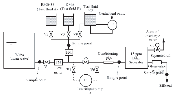
Test Rig
1.2.3 The tests should be carried out with a supply
rate equal to the full throughput for which the 15 ppm Bilge Separator
is designed.
1.2.4 Tests should be performed using three grades
of test fluids
-
.1
Test Fluid "A" which is a marine
residual fuel oil in accordance with ISO 8217, type RMG 35 (density
at 15°C not less than 980 kg/m3)
-
.2
Test Fluid "B" which is a marine
distillate fuel oil in accordance with ISO 8217, type DMA (density
at 15°C not less than 830 kg/m3).
-
.3
Test Fluid "C" which is a mixture
of an oil-in-fresh water emulsion, in the ratio whereby 1 kg of the
mixture consists of
-
947.8 g of fresh water;
-
25.0 g of Test Fluid "A"
-
25.0 g of Test Fluid "B";
-
0.5 g surfactant (sodium salt of dodecylbenzene sulfonic
acid) in the dry form;
-
1.7 g "iron oxides" (The term "iron oxide" is used to describe
black ferrosoferric oxide (Fe3 O4) with a particle
size distribution of which 90% is less than 10 microns, the remainder
having a maximum particle size of 100 microns);
Note Procedure for preparing Test Fluid C: (see example calculation)footnote
Note
1. The tank should be of a cylindrical shape.
The level of the water should be:
- 2D ≥ H ≥ 0.5D, when preparing Test Fluid "C".
Note
2. Outlet going to centrifugal pump B should
be placed at as low a position to the tank as possible.
Note
3. Inlet to the tank should be fitted at the
center of tank bottom so that the mixture flows upward to obtain uniform
and stable emulsion.
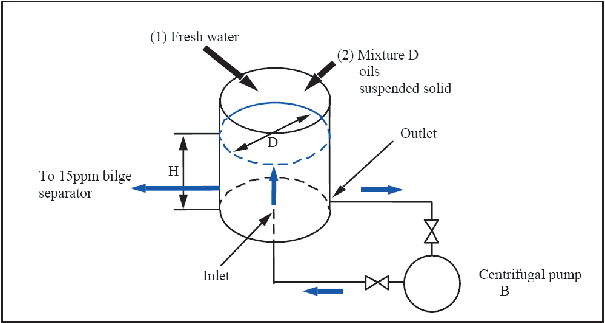
Tank of Test Fluid "C"
If the 15 ppm Bilge Separator is fitted with heating facilities
to allow the separated oil retained in it to be discharged when the
automatic discharge valve is activated, the Certificate of Type Approval
should be endorsed under the heading "Limiting Conditions Imposed"
with the following statement:
| "The 15 ppm
separator is fitted with heating facility."
|
1.2.5 If the 15 ppm Bilge Separator includes an
integrated feed pump, this 15 ppm Bilge Separator should be tested
with that pump supplying the required quantity of Test Fluid and water
to the 15 ppm Bilge Separator at its rated capacity.
If the 15 ppm Bilge Separator is to be fed by the ship's
bilge pumps, then the unit will be tested by supplying the required
quantity of Test Fluid and water mixture to the inlet of a centrifugal
pump operating at not less that 1,000 rpm (see dotted line in figure 2). This pump should have
a delivery capacity of not less than 1.1 times the rated capacity
of the 15 ppm Bilge Separator at the delivery pressure required for
the test. The variation in Test Fluid/water ratio will be obtained
by adjusting valves on the Test Fluid and water suction pipes adjacent
to the pump suction, and the flow rate of Test Fluid and water or
the Test Fluid content of the supply to the 15 ppm Bilge Separator
should be monitored. If a centrifugal pump is used, the excess pump
capacity should be controlled by a throttle valve on the discharge
side of the pump.
In all cases, to ensure uniform conditions, the piping arrangements
immediately prior to the 15 ppm Bilge Separator should be such that
the influent to the 15 ppm Bilge Separator should have a Reynolds
Number of not less than 10,000 as calculated in fresh water, a liquid
velocity of not less than 1 metre per second and the length of the
supply pipe from the point of Test Fluid injection to the 15 ppm Bilge
Separator should have a length not less than 20 times its diameter.
A mixture inlet sampling point and a thermometer pocket should be
provided near the 15 ppm Bilge Separator inlet and an outlet sampling
point and observation window should be provided on the discharge pipe.
1.2.6 In order to approach isokinetic sampling
- i.e. the sample enters the sampling pipe at stream velocity the
sampling arrangement should be as shown in figure 4 and, if a cock is fitted,
free flow should be effected for at least one minute before any sample
is taken. The sampling points should be in pipes running vertically.
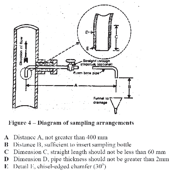
Diagram of sampling arrangements
1.2.7 In the case of the 15 ppm Bilge Separator
depending essentially on gravity, the feed to the system of the test
water and Test Fluid mixture should be maintained at a temperature
not greater than 40°C, and heating and cooling coils should be
provided where necessary. The water shall have a density of not more
than 1,015 at 20°C. In other forms of separation where the dependence
of separation efficiency on temperature is not established, tests
should be carried out over a range of influent temperatures representing
the normal shipboard operating range of 10°C to 40°C or should
be taken at a temperature in this range where the separation efficiency
is known to be worst.
1.2.8 In those cases where, for the 15 ppm Bilge
Separator, it is necessary to heat water up to a given temperature
and to supply heat to maintain that temperature, the tests should
be carried out at the given temperature.
1.2.9 The tests with Test Fluid "A" should be
carried out as follows:
-
.1 To ensure that the 15 ppm Bilge Separator commences
the test with the oil section full of Test Fluid and with the supply
line impregnated with Test Fluid, the 15 ppm Bilge Separator should,
after filling with water (density at 20°C not more than 1,015)
and while in the operating condition, be fed with pure Test Fluid
for not less than 5 min.
-
.2 The 15 ppm Bilge Separator should be fed with
a mixture composed of between 5,000 and 10,000 ppm of Test Fluid in
water until steady conditions have been established. Steady conditions
are assumed to be the conditions established after pumping through
the 15 ppm Bilge Separator a quantity of Test Fluid/water mixture
not less than twice the volume of the 15 ppm Bilge Separator. The
test should then proceed for 30 min. Samples should be taken at the
effluent outlet at 10 min and 20 min from the start of this period.
At the end of this test, an air cock should be opened on the suction
side of the pump and, if necessary, the oil and water valves should
be slowly closed together, and a sample taken at the effluent discharge
as the flow ceases (this point can be checked from the observation
window).
-
.3 A test identical to that described in 1.2.9.2,
including the opening of the air cock, should be carried out with
a mixture composed of approximately 25%footnote Test Fluid and 75%footnote water.
-
.4 The 15 ppm Bilge Separator should be fed with
100%footnote of Test Fluid for at least
5 min during which time the observation window should be checked for
any oil discharge. Sufficient Test Fluid should be fed into the 15
ppm Bilge Separator to operate the automatic oil discharge valve.
After the operation of the oil discharge valve, the test should be
continued for 5 min using a 100%footnote Test
Fluid supply in order to check the sufficiency of the oil discharge
system.
-
.5 The 15 ppm Bilge Separator should be fed with
water (density at 20°C not more than 1,015) for 15 min. Samples
of the separated water effluent are taken at the beginning of the
test and after the first 10 min.
-
.6 A test lasting a minimum of 2 h should be carried
out to check that the 15 ppm Bilge Separator will operate continuously
and automatically. This trial should use a cycle varying progressively
from water to oily mixture with approximately 25%.footnote Test Fluid content and back to water
every 15 minutes, and should test adequately any automatic device
which is fitted. The whole test sequence should be performed as a
continuous programme. At the end of the test, while the 15 ppm Bilge
Separator is being fed with 25%footnote Test
Fluid, a water effluent sample should be taken for analysis.
1.2.10 The tests with Test Fluid "B" should be
carried out as follows:
-
.1 The 15 ppm Bilge Separator should be fed with
a mixture composed of between 5,000 and 10,000 ppm of Test Fluid in
water until steady conditions have been established. Steady conditions
are assumed to be the conditions established after pumping through
the 15 ppm Bilge Separator a quantity of Test Fluid/water mixture
not less than twice the volume of the 15 ppm Bilge Separator. The
test should then proceed for 30 min. Samples should be taken at the
effluent outlet at 10 min and 20 min from the start of this period.
At the end of this test, an air cock should be opened on the suction
side of the pump and, if necessary, the oil and water valves should
be slowly closed together, and a sample taken at the effluent discharge
as the flow ceases (this point can be checked from the observation
window).
-
.2 A test identical to that described in 1.2.10.1,
including the opening of the air cock, should be carried out with
a mixture composed of approximately 25%.footnote Test Fluid and 75%footnote water.
1.2.11 The tests with Test Fluid "C" should be
carried out as follows:
-
.1 The 15 ppm Bilge Separator should be fed with
a mixture composed of 6% Test Fluid "C" and 94% water to have emulsified
oil content of 3,000 ppm in the test water until steady conditions
have been established. Steady conditions are assumed to be the conditions
established after pumping through the 15 ppm Bilge Separator a quantity
of Test Fluid "C"/water mixture not less than twice the volume of
the 15 ppm Bilge Separator.
-
.2 The test should then proceed for 2.5 h. Samples
should be taken at the effluent outlet at 50 minutes and 100 minutes
after conditioning. At the end of this test, an air cock should be
opened on the suction side of the pump and, if necessary, the Test
Fluid "C" and water valves should be slowly closed together, and a
sample taken at the effluent discharge as the flow ceases (this point
can be checked from the observation window).
1.2.12 Sampling should be carried out as shown
in figure 4 so that the sample taken will suitably represent the fluid
issuing from the effluent outlet of the 15 ppm Bilge Separator.
1.2.13 Samples should be taken in accordance with
ISO 9377-2:2000. The sample is to be extracted on the same day of
collection, and be sealed and labelled in the presence of a representative
of the national authority and arrangements should be made for analysis
as soon as possible and in any case within seven days provided the
samples are being kept between 2°C and 6°C at laboratories
approved by the Administration.
1.2.14 The oil content of the samples should be
determined in accordance with part 4 of the annex.
1.2.15 When accurate and reliable oil content
meters are fitted at inlet and outlet of the 15 ppm Bilge Separator,
one sample at inlet and outlet taken during each test will be considered
sufficient if they verify, to within ±10%, the meter readings
noted at the same instant.
1.2.16 In the presentation of the results, the
following data testing methods and readings should be reported:
-
.1 Properties of test fluids A and B:
- density at 15°C;
- kinematic viscosity (centistokes @ 100°C /40°C);
- flashpoint;
- ash; and
- water content;
-
.2 Properties of Test Fluid C:
- type of surfactant;
- particle size percentage of the non soluble suspended solids;
and
- surfactant and iron oxide quality verification;
-
.3 Properties of the water in the water tank:
- density of water at 20°C; and
- details of any solid matter present;
-
.4 Temperature at the inlet to the 15 ppm Bilge
Separator;
-
.5 A diagram of the test rig;
-
.6 A diagram of the sampling arrangement; and
-
.7 The method used in analysis of all samples
taken and the results thereof, together with oil content meter readings,
where appropriate.
|