2.1 PARAGRAPH 1.3
Interpretation
A "combined chemical/oil tanker complying with the provisions of the
IBC
Code" is a tanker that holds both a valid IOPP certificate as a tanker
and a valid certificate of fitness for the carriage of dangerous chemicals in bulk,
i.e. a tanker that is certified to carry both oil cargoes under MARPOL Annex I and Chemical cargoes in chapter
17 of the IBC Code either as full or part cargoes. The Technical
provisions should be applied to ballast tanks of combined chemical/oil tankers
complying with the provisions of the IBC
Code.
2.2 PARAGRAPH 1.4
Interpretation
1 In the context of the above requirement, the deviation should be applied only to
distances between integrated permanent means of access that are the subject of
paragraph 2.1.2 of table 1.
2 Deviations should not be applied to the distances governing the installation of
under-deck longitudinal walkways and dimensions that determine whether permanent
access is required or not, such as height of the spaces and height to elements of
the structure (e.g. cross-ties).
2.3 PARAGRAPH 3.1
Interpretation
The permanent means of access to a space can be credited for the permanent means of
access for inspection.
Technical background
The Technical provisions specify means of access to a space and to hull structure for
carrying out overall and close-up surveys and inspections. Requirements of means of
access to hull structure may not always be suitable for access to a space. However,
if the means of access to a space can also be used for the intended surveys and
inspections such means of access can be credited for the means of access for use for
surveys and inspections.
2.4 PARAGRAPH 3.3
Interpretation
1 Sloping structures are structures that are sloped by 5 or more degrees from
horizontal plane when a ship is in an upright position at even-keel.
2 Guard rails should be fitted on the open side and should be at least 1,000 mm in
height. For stand-alone passageways guard rails should be fitted on both sides of
these structures. Guardrail stanchions are to be attached to the permanent means of
access. The distance between the passageway and the intermediate bar and the
distance between the intermediate bar and the top rail should not be more than 500
mm.
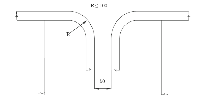
3 Discontinuous top handrails are allowed, provided the gap does not exceed 50 mm.
The same maximum gap is to be considered between the top handrail and other
structural members (i.e. bulkhead, web frame, etc.). The maximum distance between
the adjacent stanchions across the handrail gaps is to be 350 mm where the top and
mid handrails are not connected together and 550 mm when they are connected
together. The maximum distance between the stanchion and other structural members is
not to exceed 200 mm where the top and mid handrails are not connected together and
300 mm when they are connected together. When the top and mid handrails are
connected by a bent rail, the outside radius of the bent part is not to exceed 100
mm (see figure below).
4 Non-skid construction is such that the surface on which personnel walks provides
sufficient friction to the sole of boots even if the surface is wet and covered with
thin sediment.
5 "Substantial construction" is taken to refer to the as-designed strength as well as
the residual strength during the service life of the vessel. Durability of
passageways together with guard rails should be ensured by the initial corrosion
protection and inspection and maintenance during services.
6 For guard rails, use of alternative materials such as GRP should be subject to
compatibility with the liquid carried in the tank. Non-fire resistant materials
should not be used for means of access to a space with a view to securing an escape
route at a high temperature.
7 Requirements for resting platforms placed between ladders should be equivalent to
those applicable to elevated passageways.
Reference
Paragraph 10 of the annex to MSC/Circ.686/Rev.1.
2.5 PARAGRAPH 3.4
Interpretation
Where the vertical manhole is at a height of more than 600 mm above the walking
level, it should be demonstrated that an injured person can be easily evacuated.
2.6 PARAGRAPH 3.5
Interpretation
Means of access to ballast tanks, cargo tanks and spaces other than fore peak
tanks:
For oil tankers:
1 Tanks and subdivisions of tanks having a length of 35 m or more with two access
hatchways:
-
Second access hatchway:
.1 A vertical ladder may be used. In such a case where the
vertical distance is more than 6 m, vertical ladders should comprise one or
more ladder-linking platforms spaced not more than 6 m apart vertically and
displaced to one side of the ladder.
The uppermost section of the vertical ladder, measured clear of
the overhead obstructions in the way of the tank entrance, should not be
less than 2.5 m but not exceed 3.0 m and should comprise a ladder-linking
platform which should be displaced to one side of a vertical ladder.
However, the vertical distance of the uppermost section of the vertical
ladder may be reduced to 1.6 m, measured clear of the overhead obstructions
in the way of the tank entrance, if the ladder lands on a longitudinal or
athwartship permanent means of access fitted within that range. Adjacent
sections of the ladder should be laterally offset from each other by at
least the width of the ladder (see paragraph 20 of MSC/Circ.686/Rev.1 and
refer to the interpretation of paragraphs 3.13.2 and 3.13.6 of the Technical
provisions (resolution MSC.158(78))); or
-
.2 Where an inclined ladder or combination of ladders is used
for access to the space, the uppermost section of the ladder, measured clear
of the overhead obstructions in the way of the tank entrance, should be
vertical for not less than 2.5 m but not exceed 3.0 m and should comprise a
landing platform continuing with an inclined ladder. However, the vertical
distance of the uppermost section of the vertical ladder may be reduced to
1.6 m, measured clear of the overhead obstructions in the way of the tank
entrance, if the ladder lands on a longitudinal or athwartship permanent
means of access fitted within that range. The flights of the inclined
ladders are normally to be not more than 6 m in vertical height. The
lowermost section of the ladders may be vertical for the vertical distance
not exceeding 2.5 m.
2 Tanks less than 35 m in length and served by one access hatchway: an inclined
ladder or combination of ladders should be used to the space as specified in 1.2
above.
3 In spaces of less than 2.5 m in width the access to the space may be by
means of vertical ladders that comprise one or more ladder-linking platforms spaced
not more than 6 m apart vertically and displaced to one side of the ladder. The
uppermost section of the vertical ladder, measured clear of the overhead
obstructions in the way of the tank entrance, should not be less than 2.5 m but not
exceed 3.0 m and should comprise a ladder-linking platform which should be displaced
to one side of a vertical ladder. However, the vertical distance of the uppermost
section of the vertical ladder may be reduced to 1.6 m, measured clear of the
overhead obstructions in the way of the tank entrance, if the ladder lands on a
longitudinal or athwartship permanent means of access fitted within that range.
Adjacent sections of the ladder should be laterally offset from each other by at
least the width of the ladder (see paragraph 20 of MSC/Circ.686/Rev.1 and refer to
the interpretation of paragraphs 3.13.2 and 3.13.6 of the Technical provisions
(resolution MSC.158(78))).
4 Access from the deck to a double-bottom space may be by means of vertical ladders
through a trunk. The vertical distance from deck to a resting platform, between
resting platforms, or a resting platform and the tank bottom should not be more than
6 m, unless otherwise approved by the Administration.
Means of access for inspection of the vertical structure of oil tankers:
Vertical ladders provided for means of access to the space may be used for access for
inspection of the vertical structure.
Unless stated otherwise in table 1 of the Technical provisions, vertical
ladders that are fitted on vertical structures for inspection should comprise one or
more ladder-linking platforms spaced not more than 6 m apart vertically and
displaced to one side of the ladder. Adjacent sections of ladder should be laterally
offset from each other by at least the width of the ladder (see paragraph 20 of
MSC/Circ.686/Rev.1 and refer to the interpretation of paragraphs 3.13.2 and 3.13.6
of the Technical provisions (resolution MSC.158(78))).
Obstruction distances
The minimum distance between the inclined ladder face and obstructions, i.e. 750 mm
and, in the way of openings, 600 mm specified in paragraph 3.5 of the Technical
provisions, should be measured perpendicular to the face of the ladder.
Technical background
It is common practice to use a vertical ladder from the deck to the first landing to
clear overhead obstructions before continuing to an inclined ladder or a vertical
ladder displaced to one side of the first vertical ladder.
Reference
For vertical ladders: paragraph 20 of the annex to MSC/Circ.686/Rev.1.
2.7 PARAGRAPH 3.6
Interpretation
1 The vertical height of handrails should not be less than 890 mm from the centre of
the step and two course handrails need only be provided where the gap between the
stringer and the top handrail is greater than 500 mm.
2 The requirement of two square bars for treads specified in paragraph 3.6 of the
Technical provisions is based upon the specification of the construction of ladders
in paragraph 3(e) of annex 1 to resolution A.272(VIII), which addresses inclined
ladders. Paragraph 3.4 of the Technical Provisions allows for single rungs fitted to
vertical surfaces, which is considered a safe grip. For vertical ladders, when steel
is used, the rungs should be formed of single square bars of not less than 22 mm by
22 mm for the sake of safe grip.
3 The width of inclined ladders for access to a cargo hold should be at least 450 mm
to comply with the Australian AMSA Marine Orders part 32, appendix 17.
4 The width of inclined ladders other than an access to a cargo hold should be not
less than 400 mm.
5 The minimum width of vertical ladders should be 350 mm and the vertical distance
between the rungs should be equal and should be between 250 mm and 350 mm.
6 A minimum climbing clearance in width should be 600 mm other than the ladders
placed between the hold frames.
7 The vertical ladders should be secured at intervals not exceeding 2.5 m apart to
prevent vibration.
Technical background
1 Paragraph 3.6 of the Technical provisions is a continuation of paragraph 3.5 of the
Technical Provisions, which addresses inclined ladders. Interpretations for vertical
ladders are needed based upon the current standards of IMO, AMSA or the industry.
2 Interpretations 2 and 5 address vertical ladders based upon the current standards.
3 Double square bars for treads become too large for a grip for vertical ladders and
single rungs facilitate a safe grip.
4 Interpretation 7 is introduced consistently with the requirement and the
interpretation of paragraph 3.4 of the Technical provisions.
Reference
1 Annex 1 to resolution A.272(VIII).
2 Australian AMSA Marine Orders part 32, appendix 17.
3 ILO Code of Practice Safety and health in dock work – section
3.6, Access to ship's hold.
2.8 PARAGRAPH 3.9.6
Interpretation
A mechanical device such as hooks for securing at the upper end of a ladder should be
considered as an appropriate securing device if a movement fore/aft and sideways can
be prevented at the upper end of the ladder.
Technical background
Innovative design should be accepted if it fits the functional requirement with due
consideration for safe use.
2.10 PARAGRAPH 3.13.1
Interpretation
1 Either a vertical or an inclined ladder or a combination of them may be used for
access to a cargo hold where the vertical distance is 6 m or less from the deck to
the bottom of the cargo hold.
2 Deck is defined as "weather deck".
2.11 PARAGRAPHS 3.13.2 AND 3.13.6
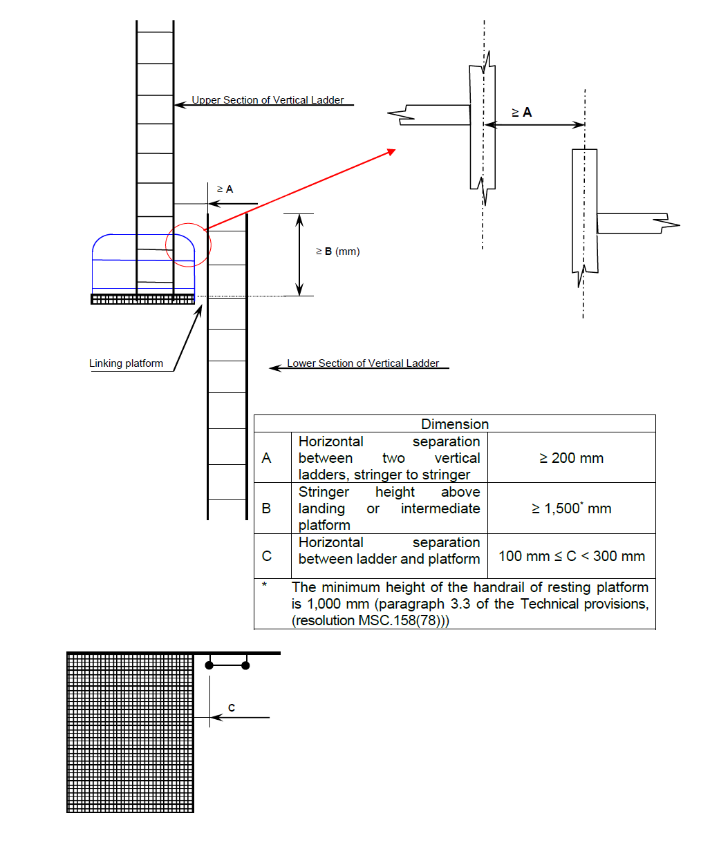
Adjacent sections of vertical ladder should be installed so that the
following provisions are complied with:
-
- the minimum "lateral offset" between two adjacent sections
of vertical ladder, is the distance between the sections, upper and
lower, so that the adjacent stringers are spaced of at least 200 mm,
measured from half thickness of each stringer;
-
- adjacent sections of vertical ladder should be installed
so that the upper end of the lower section is vertically overlapped, in
respect to the lower end of the upper section, to a height of 1,500 mm
in order to permit a safe transfer between ladders; and
-
- no section of the access ladder should be terminated
directly or partly above an access opening.
Figure "A"
Vertical Ladder – Ladder through the linking platform

Figure "B"
Vertical Ladder – Side mount
2.12 TABLE 1 – MEANS OF ACCESS FOR BALLAST AND CARGO TANKS OF OIL TANKERS,
PARAGRAPH 1.1
Interpretation
1 Sub-paragraphs .1 to .3 define access to under-deck structures, access
to the uppermost sections of transverse webs and connection between these
structures.
2 Sub-paragraphs .4 to .6 define access to vertical structures only and
are linked to the presence of transverse webs on longitudinal bulkheads.
3 If there are no under-deck structures (deck longitudinals and deck
transverses) but there are vertical structures in the cargo tank supporting
transverse and longitudinal bulkheads, access in accordance with sub-paragraphs .1
to .6 should be provided for inspection of the upper parts of vertical structure on
transverse and longitudinal bulkheads.
4 If there is no structure in the cargo tank, section 1.1 of table 1 should not be
applied.
5 Section 1 of table 1 should also be applied to void spaces in the
cargo area, comparable in volume to spaces covered by SOLAS regulation II-1/3-6, except those spaces
covered by section 2.
6 The vertical distance below the overhead structure should be measured from the
underside of the main deck plating to the top of the platform of the means of access
at a given location.
7 The height of the tank should be measured at each tank. For a tank the height of
which varies at different bays, item 1.1 should be applied to such bays of a tank
that have a height of 6 m and over.
Technical background
Interpretation 7, if the height of the tank is increasing along the length of a ship,
the permanent means of access should be provided locally where the height is above 6
m.
Reference
Paragraph 10 of the annex to MSC/Circ.686/Rev.1.
2.13 TABLE 1 – MEANS OF ACCESS FOR BALLAST AND CARGO TANKS OF OIL TANKERS,
PARAGRAPH 1.1.2
Interpretation
There is a need to provide a continuous longitudinal permanent means of access when
the deck longitudinals and deck transverses are fitted on deck but supporting
brackets are fitted under the deck.
2.14 TABLE 1 – MEANS OF ACCESS FOR BALLAST AND CARGO TANKS OF OIL TANKERS,
PARAGRAPH 1.1.3
Interpretation
Means of access to tanks may be used for access to the permanent means of access for
inspection.
Technical background
As a matter of principle, in such a case where the means of access can be utilized
for the purpose of accessing structural members for inspection there is no need of
duplicated installation of the means of access.
2.15 TABLE 1 – MEANS OF ACCESS FOR BALLAST AND CARGO TANKS OF OIL TANKERS,
PARAGRAPH 1.1.4
Interpretation
The permanent fittings required to serve alternative means of access such as wire
lift platform, that should be used by crew and surveyors for inspection should
provide at least an equal level of safety as the permanent means of access stated by
the same paragraph. These means of access should be carried on board the ship and be
readily available for use without filling of water in the tank. Therefore, rafting
should not be acceptable under this provision. Alternative means of access should be
part of the Ship Structure Access Manual which should be approved on behalf of the
flag State. For water ballast tanks of 5 m or more in width, such as on an ore
carrier, side shell plating should be considered in the same way as "longitudinal
bulkhead".
2.16 TABLE 1 – MEANS OF ACCESS FOR BALLAST AND CARGO TANKS OF OIL TANKERS,
PARAGRAPH 2.1
Interpretation
Section 2 of table 1 should also be applied to wing tanks designed as void spaces.
Paragraph 2.1.1 represents requirements for access to under-deck structures, while
paragraph 2.1.2 is a requirement for access for survey and inspection of vertical
structures on longitudinal bulkheads (transverse webs).
Technical background
SOLAS regulation II-1/3-6.2.1 requires each
space to be provided with means of access. Though void spaces are not addressed in
the technical provisions contained in resolution MSC.158(78), it is arguable whether means of
access are not required in void spaces. Means of access or portable means of access
are necessary arrangements to facilitate inspection of the structural condition of
the space and the boundary structure. Therefore, the requirements of section 2 of
table 1 should be applied to double-hull spaces even when designed as void
spaces.
2.17 TABLE 1 – MEANS OF ACCESS FOR BALLAST AND CARGO TANKS OF OIL TANKERS,
PARAGRAPH 2.1.1
Interpretation
1 For a tank, the vertical distance between horizontal upper stringer and deck head
of which varies at different sections, paragraph 2.1.1 should be applied to such
sections that fall under the criteria.
2 The continuous permanent means of access may be a wide longitudinal, which provides
access to critical details on the opposite side by means of platforms as necessary
on web frames. In case the vertical opening of the web frame is located in the way
of the open part between the wide longitudinal and the longitudinal on the opposite
side, platforms should be provided on both sides of the web frames to allow safe
passage through the web frame.
3 Where two access hatches are required by SOLAS regulation II-1/3-6.3.2, access ladders
at each end of the tank should lead to the deck.
Technical background
Interpretation 1: The interpretation of varied tank height in column 1 of table 1 is
applied to the vertical distance between horizontal upper stringer and deck head for
consistency.
2.18 TABLE 1 – MEANS OF ACCESS FOR BALLAST AND CARGO TANKS OF OIL TANKERS,
PARAGRAPH 2.1.2
Interpretation
The continuous permanent means of access may be a wide longitudinal, which provides
access to critical details on the opposite side by means of platforms as necessary
on web frames. In case the vertical opening of the web is located in the way of the
open part between the wide longitudinal and the longitudinal on the opposite side,
platforms should be provided on both sides of the web to allow safe passage through
the web. A "reasonable deviation", as noted in paragraph 1.4 of the Technical
provisions, of not more than 10% may be applied where the permanent means of access
is integral with the structure itself.
2.19 TABLE 1 – MEANS OF ACCESS FOR BALLAST AND CARGO TANKS OF OIL TANKERS,
PARAGRAPH 2.2
Interpretation
1 Permanent means of access between the longitudinal continuous permanent means of
access and the bottom of the space should be provided.
2 The height of a bilge hopper tank located outside of the parallel part of the ship
should be taken as the maximum of the clear vertical distance measured from the
bottom plating to the hopper plating of the tank.
3 The foremost and aftmost bilge hopper ballast tanks with raised bottom, of which
the height is 6 m and over, a combination of transverse and vertical means of access
to the upper knuckle point for each transverse web, should be accepted in place of
the longitudinal permanent means of access.
Technical background
Interpretation 2: The bilge hopper tanks at fore and aft of cargo area narrow due to
raised bottom plating and the actual vertical distance from the bottom of the tank
to hopper plating of the tank is more appropriate to judge if a portable means of
access could be utilized for the purpose.
Interpretation 3: In the foremost or aftmost bilge hopper tanks where the vertical
distance is 6 m or over but installation of longitudinal permanent means of access
is not practicable, permanent means of access of combination of transverse and
vertical ladders provides an alternative means of access to the upper knuckle
point.
2.20 TABLE 2 – MEANS OF ACCESS FOR BULK CARRIERS, PARAGRAPH 1.1
Interpretation
1 Means of access should be provided to the cross-deck structures of the foremost and
aftermost part of each cargo hold.
2 Interconnected means of access under the cross deck for access to three locations
at both sides and in the vicinity of the centreline should be acceptable as the
three means of access.
3 Permanent means of access fitted at three separate locations accessible
independently, one at each side and one in the vicinity of the centreline, should be
acceptable.
4 Special attention should be paid to the structural strength where any access
opening is provided in the main deck or cross deck.
5 The requirements for a bulk carrier cross-deck structure should also be considered
applicable to ore carriers.
Technical background
Pragmatic arrangements of the means of access are provided.
2.21 TABLE 2 – MEANS OF ACCESS FOR BULK CARRIERS, PARAGRAPH 1.3
Interpretation
Particular attention should be paid to preserve the structural strength in way of
access opening provided in the main deck or cross deck.
2.22 TABLE 2 – MEANS OF ACCESS FOR BULK CARRIERS, PARAGRAPH 1.4
Interpretation
"Full upper stools" are understood to be stools with a full extension between topside
tanks and between hatch end beams.
2.23 TABLE 2 – MEANS OF ACCESS FOR BULK CARRIERS, PARAGRAPH 1.5
Interpretation
1 The movable means of access to the under-deck structure of cross deck need not
necessarily be carried on board the ship. It should be sufficient if it is made
available when needed.
2 The requirements for a bulk carrier cross-deck structure should also be considered
applicable to ore carriers.
2.24 TABLE 2 – MEANS OF ACCESS FOR BULK CARRIERS, PARAGRAPH 1.6
Interpretation
The maximum vertical distance of the rungs of vertical ladders for
access to hold frames should be 350 mm. If a safety harness is to be used, means
should be provided for connecting the safety harness in suitable places in a
practical way.
Technical background
The maximum vertical distance of the rungs of 350 mm is applied with a
view to reducing trapping cargoes.
2.25 TABLE 2 – MEANS OF ACCESS FOR
BULK CARRIERS, PARAGRAPH 1.7
Interpretation
Portable, movable or alternative means of access should also be applied
to corrugated bulkheads.
2.26 TABLE 2 – MEANS OF ACCESS FOR BULK CARRIERS, PARAGRAPH 1.8
Interpretation
Readily available means able to be transported to location in cargo hold and safely
erected by ships' crew.
2.27 TABLE 2 – MEANS OF ACCESS FOR BULK CARRIERS, PARAGRAPH 2.3
Interpretation
If the longitudinal structures on the sloping plate are fitted outside of the tank, a
means of access should be provided.
2.28 TABLE 2 – MEANS OF ACCESS FOR BULK CARRIERS, PARAGRAPH 2.5
Interpretation
1 The height of a bilge hopper tank located outside of the parallel part of the
vessel should be taken as the maximum of the clear vertical height measured from the
bottom plating to the hopper plating of the tank.
2 It should be demonstrated that portable means for inspection can be deployed and
made readily available in the areas where needed.
2.29 TABLE 2 – MEANS OF ACCESS FOR BULK CARRIERS, PARAGRAPH 2.5.2
Interpretation
A wide longitudinal frame of at least 600 mm clear width may be used for the purpose
of the longitudinal continuous permanent means of access. The foremost and aftermost
bilge hopper ballast tanks with raised bottom, of which the height is 6 m and over,
a combination of transverse and vertical means of access to the sloping plate of
hopper tank connection with side shell plating for each transverse web can be
accepted in place of the longitudinal permanent means of access.
2.30 TABLE 2 – MEANS OF ACCESS FOR BULK CARRIERS, PARAGRAPH 2.6
Interpretation
The height of web frame rings should be measured in way of side shell and tank
base.
Technical background
In the bilge hopper tank the sloping plating is above the opening, while
the movement of the surveyor is along the bottom of the tank. Therefore, the
measurement of 1 m should be taken from the bottom of the tank.