2.1 In considering the design of stairway widths
for each individual case which allow for the timely flow of persons
evacuating to the muster stations from adjacent decks above and below,
the following calculation method should be used (see figures1 and 2 ):
-
when joining two decks: W = (N1 + N2)
× 10 mm;
when joining three decks: W = (N1 + N2 +
0.5N3) × 10 mm;
when joining four decks: W = (N1 + N2 +
0.5N3 + 0.25N4) × 10 mm;
when joining five or more decks the width of the stairways should
be determined by applying the above formula for four decks to the
deck under consideration and to the consecutive deck.
- where:
|
W |
= |
= the required tread width between
handrails of the stairway. |
-
The calculated value of “W” may be reduced where
available landing area “S” is provided in
stairways at the deck level defined in subtracting “P”
from “Z”, such that:
- where:
|
Z
|
= |
= the total number
of persons expected to be evacuated on the deck being considered; |
|
P
|
= |
= the number of persons
taking temporary refuge on the stairway landing, which may be subtracted
from “Z” to a maximum value of P =
0.25 Z (to be rounded down to the nearest whole number);
|
|
S
|
= |
= the surface area
(m2) of the landing, minus the surface area necessary for
the opening of doors and minus the surface area necessary for accessing
the flow on stairs (see Figure 1);
|
|
N |
= |
= the total number of persons expected
to use the stairway from each consecutive deck under consideration;
N1is for the deck with the largest number of persons using
that stairway; N2 is taken for the deck with the next highest
number of persons directly entering the stairway flow such that when
sizing the stairway width at each deck level, N1 > N2 >
N3 > N4(see Figure
2). These decks are assumed to be on or upstream (i.e. away
from the embarkation deck) of the deck being considered.
|
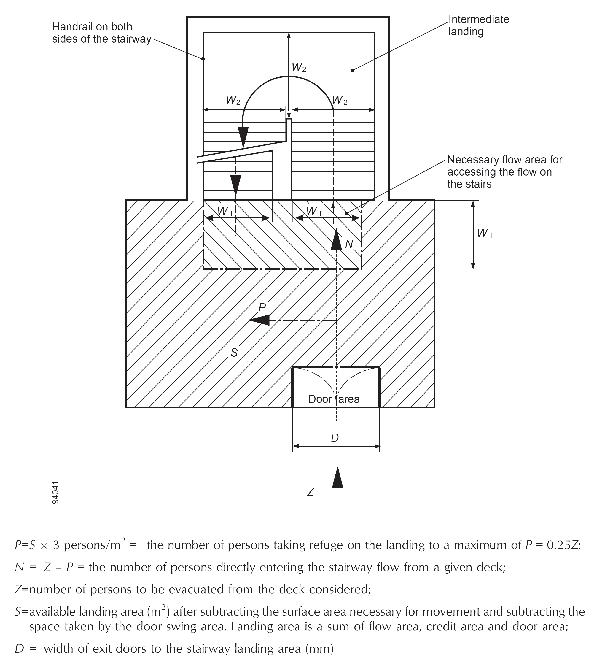
Figure 1 Landing Calculation for Stairway Width Reduction
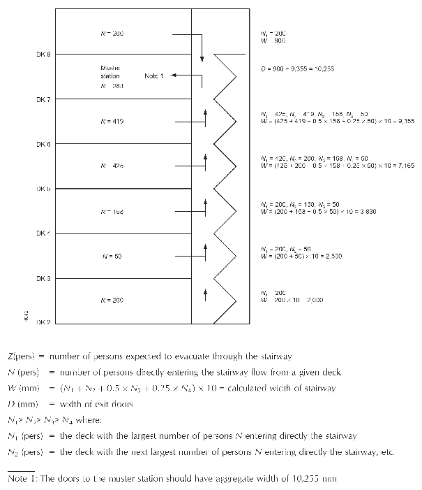
Figure 2 Minimum Stairway Width (W) Calculation Example
2.2 The stairway should not decrease in width
in the direction of evacuation to the muster station, except in the
case of several muster stations in one main vertical zone the stairway
width should not decrease in the direction of the evacuation to the
most distant muster station.
2.3 Where the passengers and crew are held at
a muster station which is not at the survival craft embarkation position
the dimensions of stairway width and doors from the muster station
to this position should be based on the number of persons in the controlled
groups. The width of these stairways and doors need not exceed 1,500
mm unless larger dimensions are required for evacuation of these spaces
under normal conditions.