1.1
Units
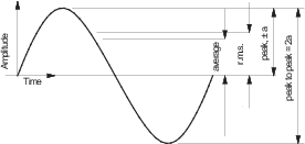
Vibration velocity amplitude (± mm/s) is adopted in these
Guidance Notes as the principal parameter for evaluating shipboard
vibration. Unless specified otherwise vibration amplitude, ±
a, is half the peak to peak value of the vibration,
Table 2.1.1 Vibration relationships for
sinusoids
.
Vibration
can also be measured in displacement or acceleration. Displacement
tends to emphasise the lower frequencies, whilst acceleration emphasises
the higher frequencies. The relationship between the three parameters
for a sinusoidal waveform is given in
Table 2.1.1 Vibration relationships for
sinusoids
. The preferred units of measurements are:
- displacement, ± mm
- velocity, ± mm/s
- acceleration, ± m/s2.
Acceleration is also commonly expressed as a ratio of the acceleration
due to gravity, “g”, where 1 g = 9.81 m/s2.
The abbreviation “Gal”, for Galileo, is sometimes encountered,
where 1 Gal = 1 cm/s2 = 10-2 m/s2.
Table 2.1.1 Vibration relationships for
sinusoids
|
Root mean square
(r.m.s.), average and peak values are related by:
|
| For a
sinusoidal waveform:
|
| displacement,
|
|
| velocity,
|
|
v |
= |
dy/dt |
| = |
(2πn).a.cos(2πn.t) |
|
| acceleration,
|
|
f |
= |
dv/dt |
| = |
d2y/dt2
|
| = |
-(2πn)2.a.sin(2πn.t) |
|
| where
|
|
1.2
Peak and
r.m.s. values
Hull structure, habitability and reciprocating machinery criteria
use the peak vibration amplitude.
The root mean square
(r.m.s.) value is related to the energy content and is used in measurements
of rotating machinery vibration.
In habitability and comfort
measurements to ISO 6954:2000 an overall weighted r.m.s. velocity
is used. In this case a frequency dependant weighting function is
applied to the measurement signal which is intended to modify the
data in a way which represents the human perception of whole-body
vibration at discrete frequencies in the range 1 to 80 Hz as detailed
in ISO 2631-2.
The units should be clearly identified.
1.3
Broadband
and narrowband
Vibration amplitudes are often measured using a simple digital
or analogue meter giving a single value representing either the peak
or r.m.s. amplitude across a range of frequencies (defined by the
characteristics of the transducer and meter). This is known as the
overall or broadband value. Conversely, a narrowband measurement is
one which is limited to a small range of frequencies usually centred
on a frequency of interest. The smallest width is determined by the
resolution of the analyser.
1.4
Conversion
of measurements
It is not possible to convert from broadband r.m.s. to peak
or vice-versa unless the individual frequencies and amplitudes (also
phase angles for r.m.s. to peak) are known. In these cases a detailed
narrowband analysis is required. The relationship between an overall
r.m.s. value xoa.rms, the r.m.s. components x1.rms,
x2.rms, x3.rms..., and the peak amplitudes x1.pk, x2.pk, x3.pk....., at frequencies 1,
2, 3,....., is as follows:
The measurement unit should be selected with care,
especially when comparison is to be made against these Guidance Notes
or international standards.
1.5
Crest factor
The crest factor is a number relating the maximum amplitude
of the waveform to the r.m.s. value. Shipboard vibration signals commonly
have crest factors between 2 and 4 if the propeller is the predominant
excitation. For a regular sinusoidal waveform the crest factor is  as defined in
Table 2.1.1 Vibration relationships for
sinusoids
.
as defined in
Table 2.1.1 Vibration relationships for
sinusoids
.
1.6
Transducers
and filters
Measurements should be made with an electronic system employing
transducers which generate signals proportional to velocity or acceleration.
Integrators may be used for conversions of velocity signals to displacement,
or acceleration signals to velocity or displacement.
Transducers
should be mounted using permanent magnets, studs, hard glue or beeswax.
Mounting surfaces should be clean and free of debris, paint, rust,
etc. Handheld probes are not recommended for single measurement applications
where good accuracy is required. They may however be used in certain
monitoring applications where care is taken to ensure repeatability.
Filters may be used to restrict the frequency range of broadband
measurements. They should be used with care to avoid attenuation and
phase change to signals.
1.7
Standards
The specifications for vibration transducers, filter characteristics,
signal conditioning, display and recording equipment and calibration
procedures should conform to International standards as listed in
Ch 11 Related Standards, references and bibliography
.
1.8
Calibration
The measuring system should be calibrated in all vibration units
of interest before and after the measurements. The calibration should
be traceable to national standards.
The characteristics
of the measuring system shall be known from calibration with regard
to the following:
- frequency response
- effect of transducer orientation and cable length
- temperature and other environmental conditions.
1.9
Records
Permanent records of vibration measurements may be in the form
of:
- Binary/ASCII computer files
- Analogue/digital magnetic tapes
- Plots of vibration spectra from a narrowband frequency analysis
- Thermal/ultra-violet oscillograph paper